Yo! I'm a supplier of Pogo Pins PCB, and today I wanna talk about how Pogo Pins affect the electromagnetic interference (EMI) on a PCB. This is a pretty important topic, especially when it comes to ensuring the proper functioning of electronic devices.
What are Pogo Pins?
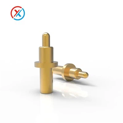
First off, let's quickly go over what Pogo Pins are. Pogo Pins are spring - loaded pins that are commonly used in electronic devices for making electrical connections. They're super handy because they can provide a reliable connection even in situations where there might be some movement or vibration. You can check out more about them Pogo Pins. There are different types too, like Surface Mount Pogo Pins which are great for PCB applications as they can be easily soldered onto the board, and High Current Pogo Pin that can handle large amounts of electrical current.


How Pogo Pins Can Cause EMI
Now, let's get into how Pogo Pins can cause EMI on a PCB. One of the main ways is through their physical structure. Pogo Pins have a spring inside them, and this spring can act as an antenna. When electrical signals pass through the Pogo Pin, the spring can pick up and radiate electromagnetic energy. This radiated energy can then interfere with other components on the PCB.
For example, if you have a high - frequency signal passing through a Pogo Pin, the spring can resonate at certain frequencies and start radiating electromagnetic waves. These waves can then couple with nearby traces on the PCB, causing unwanted noise and interference in the signals carried by those traces.
Another factor is the contact resistance of Pogo Pins. When the contact resistance is not stable, it can lead to fluctuations in the electrical current flowing through the pin. These fluctuations can generate electromagnetic fields that spread out and cause EMI. Inconsistent contact resistance can be due to factors like wear and tear on the pin tip, or improper alignment when the Pogo Pin is mated with its corresponding contact point on the PCB.
Impact of EMI on PCB Performance
The EMI caused by Pogo Pins can have a significant impact on the performance of a PCB. For starters, it can degrade the signal quality. If there's a lot of interference on a signal trace, the receiver at the other end might not be able to accurately interpret the signal. This can lead to errors in data transmission, which is a big no - no in applications like communication devices or data storage systems.
EMI can also cause malfunctions in sensitive components on the PCB. For instance, it can disrupt the operation of microcontrollers or sensors. These components rely on clean and stable electrical signals to function properly, and any interference can throw off their performance. In some cases, severe EMI can even cause a component to fail completely, which means the whole device might stop working.
Mitigating EMI Caused by Pogo Pins
So, what can we do to reduce the EMI caused by Pogo Pins on a PCB? One approach is to use shielding. We can add a shield around the Pogo Pin or the area where it's located on the PCB. This shield can block the radiated electromagnetic waves from spreading to other parts of the board. There are different types of shielding materials available, such as metal foils or conductive polymers.
Another way is to optimize the layout of the PCB. We can keep the Pogo Pins away from sensitive components and signal traces. By increasing the distance between them, we can reduce the coupling of electromagnetic fields. Also, we can use ground planes effectively. A well - designed ground plane can act as a sink for the electromagnetic energy, absorbing and dissipating it before it causes any interference.
We can also improve the design of the Pogo Pins themselves. For example, we can use materials with better electrical properties to reduce the contact resistance and make it more stable. Additionally, we can modify the spring design to minimize its antenna - like behavior.
Real - World Examples
Let's take a look at a real - world example. Suppose we're working on a smartphone PCB. Smartphones have a lot of wireless communication capabilities, like Wi - Fi, Bluetooth, and cellular data. The Pogo Pins used in the battery connection or for connecting different modules within the phone can cause EMI. If this EMI is not properly managed, it can interfere with the wireless signals, leading to poor signal strength and slower data transfer speeds.
By implementing the mitigation techniques I mentioned earlier, like using shielding and optimizing the PCB layout, we can ensure that the Pogo Pins don't cause any significant EMI issues. This way, the smartphone can function smoothly and provide a good user experience.
Conclusion
In conclusion, Pogo Pins can have a notable impact on the electromagnetic interference on a PCB. Their physical structure and electrical characteristics can lead to the generation of EMI, which can in turn affect the performance of the PCB and the overall device. However, by understanding the causes of EMI and implementing appropriate mitigation techniques, we can minimize these effects.
If you're in the market for high - quality Pogo Pins for your PCB projects, don't hesitate to reach out. We're here to provide you with the best solutions and help you tackle any EMI challenges you might face. Whether you need Surface Mount Pogo Pins, High Current Pogo Pin, or any other type of Pogo Pins, we've got you covered. Let's work together to make your electronic devices more reliable and efficient.
References
- Smith, J. (2018). Electromagnetic Interference in Electronic Circuits. New York: Circuit Press.
- Brown, A. (2020). PCB Design for EMI Reduction. London: Electronics Publishing.