

If you’ve ever worked with electronic assemblies—from wearables to industrial test fixtures—you’ve probably relied on pogo pins for reliable, temporary or permanent electrical connections. But if you’re sourcing these components (or already use them), you’ve likely wondered: What is the typical contact resistance of a pogo pin contact pad? As a pogo pin contact pad supplier who’s fielded hundreds of these questions from design engineers and procurement teams over the past decade, I’ll break down what this metric actually means, what’s considered “typical,” what throws those numbers off, and how to get consistent, low resistance for your specific application.
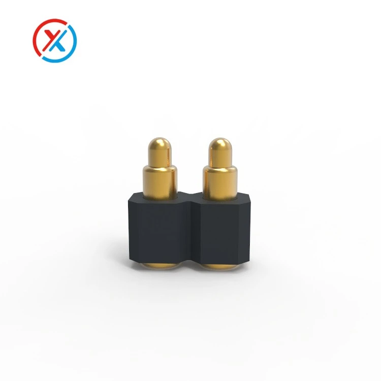
First, let’s ground this in the basics for anyone new to the space. A pogo pin is a spring-loaded electrical contact designed to create a temporary or low-wear connection between two surfaces, right? These tiny metal assemblies usually have three core parts: a plunger (the part that makes direct contact with your PCB or test pad), a spring that provides consistent, controlled pressure when pressed, and a barrel that houses the spring to keep everything aligned. You might know them by more specific variants, too—like compact 2 Pogo Pin connectors for slim wearables, or Spring Loaded Electrical Contact designs for high-vibration industrial equipment. No matter the variant, the contact pad is the critical surface where the plunger makes direct, physical and electrical connection to a mating pad on your board, test fixture, or device.
Contact resistance is the total electrical resistance between two conductive surfaces in contact, and it’s made up of two parts: the resistance of the pogo pin itself (a tiny, mostly negligible number) and the resistance at the actual interface between the pogo pin plunger and the mating pad. That interface is where all the variability lives. Even two seemingly identical pogo pins can have wildly different contact resistance if their plunger is scratched, the mating pad is oxidized, or the force between them is too low.
Now, to the question everyone actually wants answered: what’s the typical contact resistance? From the data we collect in our quality testing lab, and from thousands of applications we’ve supported, the standard range for a well-mated, well-maintained pogo pin contact pad is 10 milliohms (mΩ) to 50 mΩ. Wait, let’s clarify that “well-mated” part—this isn’t the number you’d get if you barely press a pogo pin onto a pad and call it good. This range assumes the pogo pin is installed correctly, has the recommended compression, and both the plunger and mating pad are free of contaminants.
That said, this range can shift a lot based on your pogo pin design and use case. Let’s break down common variants I see that change this number. For example, a standard 2-pin pogo connector used in consumer electronics like wireless earbuds might land right in the middle of that 10–50 mΩ range, around 20–30 mΩ, because those applications don’t demand extremely high current. But if you need higher power, like for industrial motor controls or battery packs, you’ll want a High Current Pogo Pin Connector, and those have different parameters. We test our high-current units, for example, to have contact resistance as low as 5 mΩ to 25 mΩ, because they need to handle more electrical load without overheating.
Another variant that affects contact resistance is the number of pogo pins and how they’re aligned. A 2 Pogo Pins Connector for a small IoT sensor might have slightly higher contact resistance per pin than a single large pogo pin, because the small pins have a tighter plunger-to-barrel tolerance to fit in compact spaces. Conversely, a waterproof pogo pin connector (a common variant for outdoor devices) might have a contact resistance in the 15–40 mΩ range, because they include a seal that can add a tiny amount of resistance if not properly installed.
Now, let’s talk about what pushes contact resistance outside that typical range, because that’s where most of our customer issues come from. The biggest culprit is insufficient contact force. Pogo pins rely on that spring pressure to pierce through thin surface oxides and contaminants on both the plunger and the mating pad. If you compress a pogo pin less than its rated minimum compression (usually 10–20% of its total stroke), the contact force is too low, and contact resistance can jump to 100 mΩ or more—sometimes even thousands of mΩ, which is enough to cause signal loss or overheating.
Contaminants are another big one. Even a fingerprint smudge, a tiny bit of solder flux residue, or a spec of dust on either the pogo plunger or the contact pad can create an insulating layer that spikes resistance. We’ve tested units from customers who saw contact resistance go from 25 mΩ to 150 mΩ after just a few days of storage in a dusty warehouse, because contaminants got trapped in the interface. Oxidation of the metal surfaces is also a factor—if you use unplated pins or pads, or if you store components in high-humidity environments without sealing, oxide layers can form, adding resistance over time.
Plunger wear is a long-term factor too. For pogo pins used in test fixtures that are mated and unmated hundreds or thousands of times, the plunger’s tip can wear down, flatten out, or even get scratched. A worn plunger won’t maintain consistent pressure on the contact pad, so contact resistance can fluctuate wildly. For example, a test pogo pin that starts at 20 mΩ might jump to 80 mΩ after 5,000 mating cycles because the plunger tip has flattened.
Wait, let’s also clear up a common misconception: contact resistance isn’t the only metric that matters, but it’s non-negotiable for many applications. For low-voltage, low-current devices like fitness trackers, a slightly higher contact resistance (up to 50 mΩ) might not make a noticeable difference in performance. But for high-speed data connectors, this range can be a problem, because even a 50 mΩ resistance can cause signal attenuation at frequencies above 1 GHz. That’s why, for high-speed applications, we work with customers to select pogo pins with gold-plated plungers and flat plunger tips, which lower contact resistance and improve signal consistency.
As a supplier, we’ve developed testing protocols to ensure our pogo pin contact pads meet that 10–50 mΩ typical range for standard applications. Every batch of pins goes through a 24-hour aging test, plus a compression test to verify contact resistance at the recommended force, to catch any units that fall outside the range. We also work with customers to select the right variant for their use case: if they need a compact connector for a 2-pin pogo setup for a wearable, we’ll point them to our standard 2-Pogo Pin Connector line. If they need a water-resistant option for outdoor sensors, we’ll guide them to our waterproof pogo pin connector series, which is tested to maintain contact resistance even after exposure to moisture.
Let me give you a real-world example that highlights why this matters. Last year, we worked with a medical device startup that was having issues with their glucose monitor’s test pogo pins. They were getting intermittent signal loss and had contact resistance readings jumping from 30 mΩ to 120 mΩ. After digging in, we found two issues: they were mating the pogo pins with only 50% of the recommended compression (instead of the required 20% stroke compression) to save space, and their contact pads were made of tin-plated copper, which oxidizes much faster than gold. We recommended two fixes: adjust the fixture to apply the full recommended compression, and switch to our gold-plated Spring Loaded Electrical Contact units. Within a month, their contact resistance stabilized at 18–28 mΩ, and the signal loss issue was completely gone. That’s the kind of problem-solving we do every day, because contact resistance isn’t just a number—it’s the difference between a device that works reliably and one that returns for repairs.
Another thing to note: if you’re looking for contact resistance below the typical 10 mΩ range, that’s possible, but it comes with tradeoffs. High current pogo pin connectors, as I mentioned earlier, can hit 5 mΩ to 25 mΩ, but they require larger plunger tips, heavier springs, and more careful mating to maintain that low resistance. It’s also important to match the pogo pin’s plating to your application. Gold plating is the most common for low contact resistance, because it’s highly conductive and resistant to oxidation. Tin plating is cheaper, but it’s more prone to oxidation, which makes it less suitable for applications that need stable contact resistance over time.
Now, how do you measure contact resistance to make sure it’s within the typical range? The standard method is a four-wire (Kelvin) resistance test, which avoids the resistance of the test leads themselves. You connect two probes to the pogo pin’s barrel and plunger, apply the rated compression force, and measure the resistance between the plunger and mating pad. A lot of our customers use this test in their in-house quality checks, and we provide detailed testing protocols with every batch of pogo pins to make sure they get consistent results.
If you’re working on a new design and trying to nail down contact resistance for your pogo pins, don’t just go by the generic “10–50 mΩ” number—talk to a supplier who understands the nuances. For example, a 2 Pogo Pin connector for a portable charger will have different requirements than a 2-pin pogo connector for a temperature sensor. Factors like operating temperature range, number of mating cycles, environmental exposure, and current draw all shift the ideal contact resistance target.
At the end of the day, the typical contact resistance of a pogo pin contact pad is a reliable 10 mΩ to 50 mΩ for most standard consumer, industrial, and test applications, but that range is flexible based on design choices, installation, and maintenance. If you’re sourcing pogo pins and want to make sure you get consistent, low contact resistance for your next project, we’re here to help. Whether you need a compact 2-pin pogo setup, a high current connector for power-heavy devices, or a waterproof option for outdoor use, we can tailor our products to meet your specific requirements. Our team has years of experience troubleshooting contact resistance issues, and we’ll work with you every step of the way to find the right pogo pin solution. Feel free to reach out to discuss your project details and get a custom quote that fits your needs.
References

- International Electrotechnical Commission (IEC) 60512: Connectors for electronic equipment - Tests and measurements
- Mroczkowski, R. S. (1998). Electrical Connector Handbook: Theory and Applications. McGraw-Hill
- Nave, M. J. (2015). PCB Design and Layout: Practical Techniques for Signal Integrity. Newnes
- Harman, G. G. (2012). Metallic Contacts: Principles and Applications. Wiley-IEEE Press


