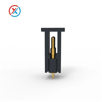
If you’re a design engineer or procurement manager working with electronic assemblies, you’ve probably encountered the frustration of intermittent electrical connections, overheating components, or devices that fail after just a few cycles. For me, this is why every product we ship as a pogo pin contact pad supplier starts with a single non-negotiable goal: consistent, reliable conductivity that holds up under real-world use. Pogo pins—those spring-loaded, precision-engineered contacts—are the quiet backbone of everything from wearable tech and medical devices to automotive sensors and consumer electronics. But their conductivity only works as well as the contact pads they interface with. I’ve spent 12 years in this space, troubleshooting everything from tiny smartwatch connections to 10A industrial power applications, and today I’m breaking down exactly how we ensure our pogo pin contact pads deliver the conductivity your designs need.
First, let’s ground this in what pogo pins and their contact pads actually do, because skimming the basics is where a lot of teams cut corners. If you’re new to these components, you can start with a deep dive on what makes them work: Spring Loaded Electrical Contact. A pogo pin itself is a tiny assembly of a plunger, spring, barrel, and end cap. When pressed into a contact pad, the spring compresses, creating a mechanical force that pushes the plunger firmly against the pad’s surface. That mechanical force is what breaks down surface barriers like oxidation and residue, allowing electrons to flow freely. But the contact pad is the foundation here—if the pad isn’t matched to your pogo pin, or isn’t manufactured to precise standards, even the best pogo pin (we specialize in high-performance variants, like those for 10A loads, found here: Pogo Pin Connectors 10A) will underperform.
Step one in ensuring conductivity is material selection, and this is where we refuse to take shortcuts. The contact pad’s material has to balance electrical conductivity, mechanical durability, resistance to corrosion, and compatibility with the pogo pin’s plunger material. I’ve seen suppliers use generic copper foils with a thin gold flash, only to have the pad oxidize within months in high-humidity environments. That’s why all our contact pads start with a high-purity copper core—either C11000 (electrolytic tough pitch copper, 99.9% pure) for general use or C10100 (oxygen-free copper) for high-frequency applications, where even tiny amounts of impurities can disrupt signal flow. The core is then plated with a layer that serves two purposes: it prevents the copper from oxidizing, and it creates a low-resistance interface with the pogo pin’s plunger. We don’t use cheap tin plating that will corrode or wear off after a few thousand cycles. For most applications, we use a 1–3 micron layer of nickel as a barrier (to stop copper diffusion into the plating that would raise resistance) followed by a 0.5–1 micron layer of gold. For high-wear applications like the 2 Pogo Pins Connector that sees thousands of mating cycles, we thicken the gold layer to 2 microns to extend service life.
Material selection isn’t just about plating thickness, though—it’s also about matching the pad’s surface finish to the pogo pin’s. If you have a pogo pin with a hard, polished tungsten plunger and a contact pad with a soft, rough surface, the plunger will cut through the pad’s plating over time, exposing the copper core to oxidation. Conversely, a soft gold pad against a hard plunger will wear away the gold plating prematurely, reducing conductivity. This is why we work closely with customers to map their exact pogo pin specs—whether that’s a standard Connector Pogo Pin for low-voltage signals or a power pogo pin for 10A loads. For example, if a customer is building a waterproof consumer device, we’ll adjust the pad’s plating to match our waterproof pogo pin designs (available here: 2-pin pogo connector) to ensure the combination resists moisture, which is one of the biggest killers of conductivity.
Next, surface preparation is non-negotiable. Even the best material will fail if the pad’s surface is covered in residue, oils from manufacturing, or microscopic pits that prevent the pogo pin from making full contact. Here’s a lesson I learned early: a contact pad that looks perfectly smooth under a magnifying glass can have tiny oil residues from the stamping process that add thousands of ohms of resistance, enough to cause intermittent connections in portable devices. Our process for cleaning contact pads is a multi-step, controlled procedure, not just a quick wipe. First, we use a mild, environmentally safe alkaline cleaner to remove organic residues from stamping and forming. Then we do a reverse-osmosis water rinse to eliminate all cleaner traces, followed by a desmut step to remove any metallic debris left from cutting the pad’s shape. Finally, we pass the pads through a dry nitrogen oven to eliminate all moisture, because even a thin layer of water on a pad’s surface can create a resistive film over time—especially in low-voltage applications where tiny resistance differences matter. We test every batch’s surface cleanliness with a surface resistance meter before it leaves our facility; if the initial surface resistance is above 0.02 ohms, it goes back for reprocessing, no exceptions.
Then there’s the critical step of dimensional precision, which directly impacts how well the pogo pin mates with the pad. A contact pad that’s too small means the pogo pin’s plunger only touches a portion of the pad’s surface, creating a high-resistance point. A pad that’s too large might work for low-load applications, but for high-current designs, the gap between adjacent pads (especially in a 2-pin connector) can cause arcing or current leakage. We hold dimensional tolerances of ±0.025mm for pad size and placement—small enough to ensure that even with the slight alignment variations common in mass-produced assemblies, the pogo pin makes full, consistent contact across the pad’s surface. We also consider the pad’s thickness: a pad that’s too thin will deform under the pogo pin’s compression force, leading to inconsistent contact over time, while a pad that’s too thick will require more force to mate, which can damage the pogo pin’s spring. For most applications, we spec pad thickness between 0.1mm and 0.2mm, calibrated to match the spring force of the pogo pin we’re supplying alongside the pad. For power applications like Pogo Pin Connectors 10A, we add a small, reinforced border around the pad to prevent deformation under higher compression forces.
Compression force and mating cycles are two more factors that people often overlook when ensuring conductivity. The pogo pin’s spring has to compress to a specific amount to create enough force to break down surface barriers, but not so much that it damages the pad. We test the combination of our pogo pins and contact pads in our in-house cycling lab, running thousands of mating cycles under load to measure contact resistance over time. For standard Spring Loaded Electrical Contact assemblies, we aim for a compression force of 15–25 grams per pin, which is enough to create a stable connection without excessive wear. For high-power Pogo Pin Connectors 10A that carry more current, we increase the compression force to 50–75 grams, ensuring that the plunger makes full, continuous contact across the pad’s surface to handle the higher current load. We also test contact resistance after cycling: if resistance increases by more than 5% over 5,000 cycles, we adjust the pad’s plating or the pogo pin’s material to improve durability. This isn’t just theoretical—we’ve had customers come to us with designs that failed after 1,000 cycles because they used low-quality pads, and we reworked their assemblies using our precision-machined pads to extend service life to over 10,000 cycles.
Corrosion resistance is the final piece of the puzzle, and it’s especially important for devices used in harsh environments, from automotive under-the-hood sensors to outdoor industrial equipment. Oxidation is the biggest enemy here: even a thin layer of copper oxide on a contact pad can increase resistance by orders of magnitude, turning a 0.01 ohm connection into a 10 ohm bottleneck that causes devices to fail. Our contact pads are sealed with a final overcoat of flux-free, inert polymer for applications that see high humidity, salt spray, or temperature extremes. This overcoat is thin enough (only 0.05 microns) that it doesn’t add significant resistance, but it prevents oxygen and moisture from reaching the pad’s metal surface. For waterproof applications like our 2-pin pogo connector, we also adjust the pad’s edge finish to be rounded, preventing water from pooling between the pad and the pogo pin during mating. We test corrosion resistance per industry standards, like ASTM B117 salt spray testing, and all our pads pass 1,000 hours of salt spray without any measurable increase in contact resistance.
I’ll be honest—there’s no magic bullet for ensuring pogo pin contact pad conductivity. It’s a combination of material selection, precision manufacturing, rigorous testing, and matching the pad to the exact application of your pogo pin. Over the years, I’ve seen so many teams cut corners on any of these steps, only to deal with field failures, returns, and delayed product launches. That’s why we’ve built our business around being a partner, not just a supplier: we work with your engineering team to specify the right pad for your Connector Pogo Pin, whether you’re building a tiny wearable or a high-power industrial assembly. We test every batch of pads for surface resistance, dimensional accuracy, and corrosion resistance, and we’ll adjust our process if your design has unique needs.
If you’re tired of intermittent connections, overheating devices, and components that fail before their time, let’s talk. Our team has the expertise to help you design contact pads that deliver consistent, reliable conductivity, no matter the application. Reach out to discuss your pogo pin and contact pad needs, and we’ll help you find the right solution for your project.
References


- US Department of Energy. (2018). Electrical Contacts: Principles and Applications. DOE Office of Energy Efficiency and Renewable Energy.
- ASTM International. (2021). Standard Test Method for Measuring Contact Resistance of Electrical Contacts (ASTM B539-21).
- Zhang, Y., & Wang, L. (2020). “Corrosion Behavior of Plated Contact Pads for Spring-Loaded Connectors.” Journal of Electronic Materials, 49(7), 4212–4220.
- International Electrotechnical Commission. (2019). IEC 60512-1-1: Connectors for Electronic Equipment – Tests and Measurements – Part 1-1: General and Miscellaneous Tests – Test 1a: Visual Examination.
- Smith, J. D. (2019). “Pogo Pin Contact Pad Design for High-Current Applications.” Proceedings of the 2019 International Conference on Electronic Packaging Technology, 1–4.