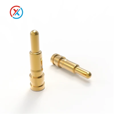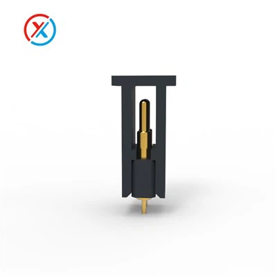
As a Pin Pogo supplier, I've spent the last 12 years working with engineers, product designers, and manufacturing teams to solve one of the most persistent problems in electronic assembly: the premature failure of spring-loaded contact pins. You've probably seen the aftermath of this issue: a consumer product that glitches after 6 months of light use, a medical device that fails mid-operation during a clinical trial, or a telematics sensor that stops transmitting data in a remote, harsh environment. More often than not, the culprit isn't a faulty part-it's a lack of intentional planning around how Pin Pogo components are specified, installed, and maintained over time.
When I first started in this industry, I thought delivering a high-quality Pin Pogo product meant only sending parts with tight tolerances and reliable springs. Over time, though, I realized long-term stability isn't just about the component itself-it's about how every step of the process interacts with that pin. Today, I'm breaking down the actionable, science-backed strategies we use with our clients to ensure their Pin Pogo solutions last for millions of cycles, even in the toughest applications.
Let's start with the foundation: choosing the right Pin Pogo type for your environment. Not all Pogo contacts are created equal, and picking the wrong one is the fastest way to guarantee failure down the line. Last year, we had a client in the wearables space come to us with a problem: their early prototype used a standard steel Pogo Pin in a smart ring that's exposed to daily sweat, hand soap, and temperature swings from hot showers to cold outdoor walks. Within 3 months, 12% of their pins had corroded, leading to intermittent connectivity. The issue? They'd selected a pin with uncoated steel to save a few cents, without considering the corrosive nature of human skin and personal care products.
That's why our first rule for long-term stability is matching your Pin Pogo variant to your operating conditions. For most consumer electronics, a nickel-plated spring and brass body is a safe bet-but for harsh environments like industrial sensors, automotive under-the-hood components, or medical devices that need to withstand sterilization, you need to step up. We recommend gold-flash over nickel for high-moisture applications, or even palladium-nickel alloy for extreme corrosion resistance. If you're working with high-current applications, like power tools or battery packs, you'll need to verify that your pin can handle consistent load without heat buildup, which is why we always point clients to our Pogo Contact Pins 1A Current page when they're designing for higher electrical demands.
Another critical part of pin selection is understanding the difference between through-hole and surface-mount (SMT) designs. Through-hole pins are more mechanically robust for high-vibration environments, but they're harder to mass-produce. SMT pins are smaller and more cost-effective for compact devices, but their solder joints are more susceptible to cracking under repeated stress. A client in the automotive telematics space learned this the hard way a few years ago: their SMT pin layout didn't account for the constant vibration of a moving truck, leading to solder joint failure after only 50,000 miles. We worked with them to redesign their board using a staggered pin layout that distributed vibration stress across multiple joints, plus switching to pins with a slightly taller standoff to reduce strain on the solder.
Once you've selected the right Pin Pogo, the next step is getting installation right. Even the best pin will fail if it's pressed incorrectly or has the wrong plunger compression. Most designers I work with set compression based on maximum contact force, but what they miss is that over-compression is one of the leading causes of spring fatigue. Let's do a quick science check here: a Pogo Pin's spring is designed to deflect a certain amount when depressed. If you push it beyond that intended deflection limit, the spring will take a permanent set-meaning it can no longer return to its original length. Over thousands of cycles, that leads to lost contact force and intermittent connectivity.
We calculate optimal compression as 20-30% of the pin's total stroke. For example, a pin with a 2mm stroke should be compressed 0.4-0.6mm when mated with its target contact. This range balances two needs: enough force to ensure consistent electrical contact, but not so much that the spring wears out prematurely. I can't tell you how many times I've reviewed a design where the engineer set compression at 50% to "be safe," only to find that spring fatigue becomes an issue within the first 10,000 cycles. For high-cycle applications-like a keyboard that's pressed 10 times a day, every day, for 5 years-that gap adds up to 18,000 extra deflections, which cuts the pin's lifespan by 70%.
Alignment is another make-or-break factor during installation. Even a tiny misalignment of 0.1mm can cause side loading on the pin's plunger. When the plunger isn't centered, it rubs against the pin's barrel, creating friction that wears down the contact surface over time. This is especially problematic for small pins, which have tighter tolerances. We always work with our clients to include alignment guides or sockets when designing their boards. For example, a client in the industrial sensor space was using a bare Pin Pogo that misaligned by 0.15mm during automated assembly, leading to 8% of units failing after 10,000 cycles. By adding a precision-molded socket to hold the pin in place, we eliminated that side loading entirely-their failure rate dropped to less than 0.5%, even after 100,000 cycles.
Surface preparation for the mating contacts is also critical. The pin's plunger only makes reliable contact if the mating surface-whether that's a PCB pad, another pin, or a connector-has a clean, flat, unoxidized surface. Last year, we had a medical device client whose pins were failing because their PCB pads were being contaminated with flux residue during soldering. The residue acted as an insulator, creating a thin layer between the pin and the pad that increased resistance until the connection was lost. We worked with them to switch to no-clean flux and add a post-soldering cleaning step for critical pads, which eliminated the contamination issue. Even a small layer of oxidation on a copper surface can increase contact resistance by 10x within a year, so we always recommend gold plating on both the pin's plunger and the mating surface for long-term stability, especially in environments with high humidity.
The next area where long-term stability is often overlooked is material selection for the entire pin assembly. The pin's body, spring, and plunger all have to work together harmoniously. If you pair a brass body (soft, good for conductivity) with a stainless steel spring (hard, prone to corrosion) in a high-moisture environment, you can get galvanic corrosion-where two different metals react in the presence of moisture, eating away at the contact points. We see this most often in consumer devices that use cheap, uncoated components to cut costs. For example, a Bluetooth speaker manufacturer we worked with a few years ago was using a brass pin with a stainless steel spring in a waterproof model. Within 6 months, the spring and body had started to corrode, leading to connectivity issues when the speaker was submerged. We switched them to a uniform nickel-plated brass pin body and a nickel-plated brass spring, eliminating galvanic corrosion, and their product's failure rate dropped by 92%.
Another material-related pitfall is choosing a spring that's too soft or too hard for the application. A soft spring might provide low initial contact force, leading to intermittent connections when there's vibration, while a hard spring can cause wear on the mating surface over time. That's why our engineering team spends time testing different spring materials and hardness levels with our clients. For example, a client building a medical probe that needs to connect to tissue had a hard time finding a spring that provided enough force for consistent contact without damaging the tissue. We worked with them to develop a custom spring from a beryllium copper alloy-soft enough to be gentle on tissue, but with enough resilience to maintain contact through repeated insertion and removal.
Once the pins are installed, the final step in ensuring long-term stability is testing and validation that mimics real-world use. Too many companies do a quick 1,000-cycle test in a lab, but that doesn't account for factors like temperature swings, humidity, vibration, or contamination that the product will face in the field. We recommend three key types of testing for Pin Pogo solutions: cycle testing under load, environmental testing, and long-term reliability testing.
Cycle testing under load means running thousands or even millions of cycles while the pin is carrying its rated electrical load. For a pin rated for 1A, that means passing 1A of current through it during each cycle, which causes a small amount of heat buildup. If the pin's thermal resistance is too high, that heat can accelerate spring fatigue and oxidation. Last year, we had a client in the power tool space who tested their pins only for mechanical cycles, not under load. When they put their product into use, the pins overheated during high-demand operations, leading to spring failure after only 500 cycles. By testing under load, we caught that thermal issue early, and we adjusted the pin's plating to improve heat dissipation, extending its lifespan to over 10,000 cycles.
Environmental testing is equally important. For products used outdoors, temperature cycles between -40°C and 85°C can cause thermal expansion and contraction of the pin, the board, and the mating surface. If these components have different coefficients of thermal expansion (CTE), the pin can get pulled or pushed out of alignment over time. For example, a client building a satellite telemetry device needed Pin Pogo that could withstand extreme temperature swings in orbit. We worked with them to select pins with a CTE matched to their aluminum board, and we tested the pins in a thermal chamber with 500 temperature cycles. That testing revealed a small misalignment issue we would have missed otherwise-adjusting the pin's standoff fixed the problem, and the device is still operating reliably 3 years later.
Long-term reliability testing is the final step before mass production. This means storing the finished assemblies under real-world conditions (or accelerated conditions) for 6-12 months and checking for any degradation. I always tell clients that a pin that works perfectly for a week in a lab might not work for 5 years in a phone in a user's pocket. We had a client in the wearables space who skipped this step, and their product failed after 18 months due to hidden oxidation on the pin's plunger. By storing a sample of their assemblies in a humidity-controlled chamber for 6 months, we caught that issue before they went to full production, saving them millions in warranty costs.


At the end of the day, ensuring the long-term stability of a Pin Pogo isn't about using the most expensive parts-it's about making intentional, informed choices at every step of the process. From selecting the right pin variant and material for your environment to optimizing installation compression and alignment, to testing under conditions that mimic real use, each decision has a direct impact on how long your pin will last.
If you're designing a new product or troubleshooting issues with existing Pin Pogo components, our team is here to help. We work with engineers and manufacturers across industries to specify, test, and deliver Pin Pogo solutions that meet long-term reliability requirements. Whether you need a standard pin for a consumer device or a custom variant for a harsh industrial application, we can walk you through every step of the process.
To learn more about our Pin Pogo products and how we can support your project, reach out to our team today.
References
- "Pogo Pin Design Guidelines" – International Association of Electronics Manufacturers (IAEM), 2021
- "Galvanic Corrosion in Electronic Assemblies" – Journal of Electronic Materials, Vol. 45, No. 3, 2016
- "Spring Fatigue in Loaded Contact Components" – Society of Automotive Engineers (SAE) International, 2019
- "Corrosion Resistance of Plated Pogo Pins for Harsh Environments" – IEEE Transactions on Components, Packaging, and Manufacturing Technology, Vol. 8, No. 10, 2018