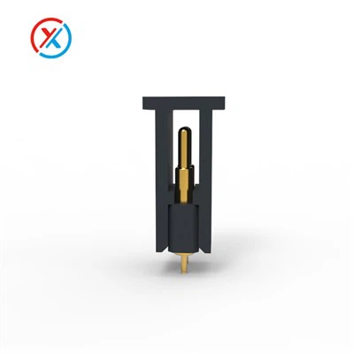
If you’ve ever sourced pogo pin contact pads for high-performance electronics, you know that contact resistance isn’t just a technical metric—it’s the difference between a battery that charges reliably and one that fails after a few cycles, a circuit board that passes QA and one that gets scrapped, or even a medical device that operates as intended instead of risking patient safety. As a long-time supplier of pogo pin solutions, I’ve seen too many projects derail from lazy contact resistance testing: rushed measurements, uncalibrated tools, or tests that ignore the unique variables of spring-loaded contacts, not fixed electrical connections. Over the years, I’ve refined a process that balances scientific rigor with practicality, and today I’m breaking down how to measure contact resistance accurately, straight from the perspective of someone who ships these parts to engineers designing everything from wearables to industrial sensors.
First, let’s make sure we’re all on the same page: contact resistance is the small, unwanted electrical resistance that forms at the interface between a pogo pin’s tip (or plunger) and a mating contact pad. It’s not the resistance of the pogo pin itself (which is usually less than 10 milliohms for high-quality units) or the pad’s bulk resistance. Instead, it comes from two main sources: the thin layer of contamination (oil from manufacturing, oxidation, or dust) on both the pin and pad surfaces, and the microscopic asperities—tiny bumps and valleys—on their mating faces, which only make physical contact at a handful of points, creating narrow, high-resistance current paths.
For context, the spring-loaded design of a pogo pin is critical here. Unlike a solid pin that presses into a pad, a spring allows the pin to exert consistent, controlled force on the pad, which compresses those asperities and breaks through surface contamination to create a stable connection. That’s why understanding how to measure this force alongside resistance is non-negotiable—skip the force variable, and your measurements will be meaningless. This is where the first key link to our product line matters: our Spring Loaded Electrical Contact pages detail exactly how our pogo pins are engineered to maintain consistent force across millions of insertions, a foundation that makes accurate contact resistance testing possible.
Before we dive into the test steps, there are a few common mistakes that even experienced engineers make that skew results. The biggest? Using a generic multimeter with two leads, testing the contact resistance as a static value without accounting for force or current. That method will give you wildly inconsistent readings—one test might measure 5 milliohms, another 20, because the pin wasn’t pressed with the same force, or the test current was too low to overcome surface contamination. Another mistake? Testing only new parts, ignoring how contact resistance changes after repeated use. For many applications, like Pogo Pin Connectors 10A (used in power-hungry devices like portable chargers), contact resistance after 10,000 insertions could be the make-or-break factor, not just the first test. A third error is testing in ideal lab conditions (dry, temperature-controlled, no static) and shipping parts that perform differently in a warehouse with variable humidity.

Now, let’s get to the step-by-step process I use with my team and share with our customers. We structure our testing around four core components: a test fixture that replicates real-world force, a measurement tool with sufficient current, a standardized test pad, and a method to eliminate measurement errors inherent in two-probe setups.
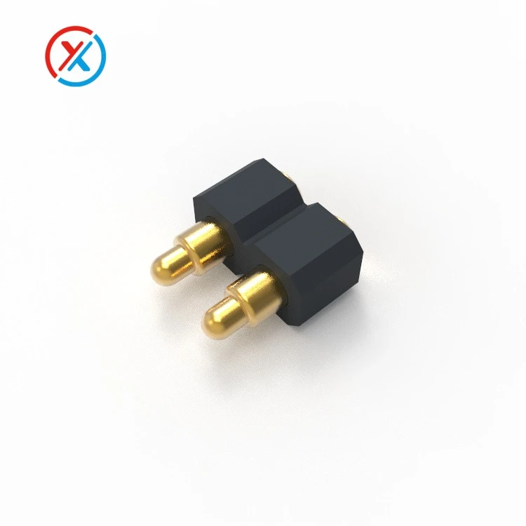
First, build or source a test fixture that matches your application’s force requirements. Not all pogo pins exert the same force—small pins for wearables might use 50 grams of force, while high-power pins for electric vehicle components can use 500 grams or more. For accurate testing, the fixture must apply a known, constant force to the pogo pin and test pad. We’ve seen customers try to use a simple weight on top of a pin, but that’s unreliable—weights can shift, and they don’t account for the spring’s compression curve. Instead, use a linear actuator with a force sensor, calibrated to apply the exact force your product needs. For example, if you’re testing our 2-pin pogo connector (perfect for space-constrained applications), the fixture should replicate the mating force between those two pins and their corresponding pads.
Second, choose the right measurement tool and current. Two-probe multimeters are fine for rough checks, but they suffer from the “lead resistance” problem—your test leads add their own tiny resistance to the measurement, which can be significant if you’re measuring contact resistance values that are just a few milliohms. Instead, use a four-wire (Kelvin) measurement tool, which separates the current-carrying leads from the voltage-sensing leads, eliminating lead resistance from the calculation. Equally important is the test current: the Kelvin method works best when you use the rated operating current of your pogo pin. For low-current applications, that might be 10 mA, but for high-power applications like our Pogo Pin Connectors 10A, you’ll need at least 1 A to get a consistent, stable measurement that breaks through surface oxides and contamination. Too little current, and the contact resistance will appear artificially high—like trying to measure the width of a straw with a very wide stick.
Third, prepare standardized test pads and control variables. If you’re testing your own contact pads, make sure they match the material, plating, and surface finish of the pads your product will use. Gold plating is standard for pogo pin contacts because it’s corrosion-resistant, but even gold can have a 1-2 microinch thick oxide layer that adds resistance. Also, control the environment: test at the same temperature and humidity your product will operate in, since humidity can cause surface oxidation, and temperature changes affect both the pin’s spring tension and the pad’s conductivity. If you’re testing multiple batches of pins, test 20-50 units per batch to account for manufacturing variation—one bad pin can skew your average result. We make it easy for customers to get standardized test pads by linking to our Spring Loaded Electrical Contacts pages, which include recommended pad dimensions and plating specifications that work seamlessly with our pins.
Fourth, run the test sequence to mimic real-world use. Don’t just press the pin onto the pad once and call it a day. Start with a pre-test break-in step: cycle the pin on and off the test pad 10 times at a consistent force, then test the resistance on the 10th cycle. This simulates the first few insertions, which can scrape off loose surface contamination and create a stable interface. Then, measure both the initial contact resistance (right after the 10th cycle) and the resistance after a 1-minute hold at the rated force—this tests for any voltage drift, a common issue with contact interfaces. For applications that involve repeated use, run a cycle test: 1,000 insertions, then test the resistance again. This tells you if the contact is degrading over time, which is critical for products like consumer electronics that get plugged in and out thousands of times a year.
Once you have your measurements, how do you know if they’re accurate? A good rule of thumb for high-quality pogo pins is that contact resistance should be less than 10 milliohms for low-current applications and less than 5 milliohms for high-current (10A+) use. If your measurements are higher than that, it could mean a few things: the pin isn’t applying enough force, the test current is too low, or the pad or pin surface has excessive contamination. To verify your measurement setup, run a control test with a known standard resistor (like a 10 milliohm precision resistor) and make sure your Kelvin tool measures it within 1% of the stated value. If it doesn’t, your tool needs calibration—this is one of the easiest fixes, but it’s often overlooked.
Over the years, I’ve found that the biggest advantage of working with a pogo pin supplier is that we can tailor testing to your specific product. For example, if you’re designing a waterproof device that uses our waterproof pogo pin connector (linked in our 2-pin pogo connector page), we can test contact resistance after exposing the pins to water spray, a variable that many standard tests ignore. If you’re working on a low-power IoT sensor, we can test at 1 mA current to match your device’s operating profile, instead of using a generic 1 A current that won’t reflect real-world performance.
I also want to address a common question from engineers: why does contact resistance matter so much? Let’s put it in practical terms. A smartphone that uses a pogo pin for wireless charging relies on a contact resistance of less than 5 milliohms—if it’s 15 milliohms, the charging time could increase by 30%, or the device could overheat. A medical wearable that transmits heart rate data via pogo pins needs consistent contact resistance to avoid dropped data packets. Even industrial sensors, which operate in harsh environments, need contact resistance that stays stable over 100,000 insertions to avoid downtime on a factory floor.
If you’re still relying on ad-hoc contact resistance testing for your pogo pin contact pads, it’s time to formalize your process. The key takeaways are: use Kelvin (four-wire) measurements, apply consistent force, test at your rated operating current, and account for real-world use cycles. For more details on how our products are tested, check out our Spring Loaded Electrical Contact pages, where you’ll find product specs tailored to both low and high-power applications. Our 2 Pogo Pin Connector line, for example, is designed for high-reliability applications, with contact resistance testing that meets IPC standards for electronic components.
At the end of the day, accurate contact resistance testing isn’t just a technical step—it’s a way to avoid costly reworks, late shipments, and products that fail in the field. If you’re working on a project that requires reliable pogo pin contacts, we can help you design test setups that fit your needs, or provide custom-tested pins that meet your exact resistance requirements. Don’t hesitate to reach out to our team to discuss your application and find the right pogo pin solution for your project.
References
- IPC-9201, “Test Method for Measuring Contact Resistance of Electrical Connectors,” IPC Association Connecting Electronics Industries, 2019.
- Greenwood, J. A., and Williamson, J. B. P., “Contact of Nominally Flat Surfaces,” Proceedings of the Royal Society of London. Series A, Mathematical and Physical Sciences, Vol. 200, No. 1063, 1950, pp. 300–319.
- “Pogo Pin Connector Design Guidelines,” Tech Briefs for Precision Interconnects, Amphenol ICC, 2022.
- ASTM B457-19, “Standard Test Method for Measuring Electrical Contact Resistance of Electrical Contacts,” ASTM International, 2019.
- Li, Y., et al., “Reliability of Spring-Loaded Electrical Contacts Under Cyclic Insertion,” IEEE Transactions on Components, Packaging and Manufacturing Technology, Vol. 12, No. 10, 2022, pp. 1542–1550.