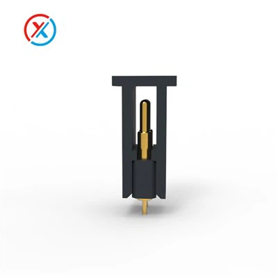
If you’ve ever designed a portable electronic device, worked on charging systems, or sourced custom connectivity components, you’ve likely encountered pogo pins: those tiny, spring-loaded metal contacts that create reliable, repeatable electrical connections without soldering or pins that wear out after a few insertions. For us, as a USB pogo pin supplier, one of the most common questions we get from engineers and product designers is about impedance matching—and for good reason. Impedance mismatches in USB pogo pins can be a silent killer of device performance, leading to slow charging, data corruption, overheating, or even complete connectivity failure. Let’s break down what impedance matching means for USB pogo pins, why it matters, how we approach it here at our facility, and how to get it right for your next project.
First, let’s ground this in basic terms, no jargon overload. Impedance is the total opposition that a circuit (or component, like a pogo pin) offers to the flow of alternating current (AC) or high-frequency signals. Unlike direct current (DC), which flows steadily, USB data signals—even standard USB 2.0 or USB-C—are high-frequency AC signals that oscillate millions of times per second. Think of it like water flowing through a hose: if the hose’s diameter suddenly narrows or widens, the water can’t flow smoothly; some splashes back, causing wasted energy or pressure drops. That’s exactly what happens with signals when impedance doesn’t match. For USB, the target impedance is almost always 90 ohms for differential pairs (the pair of wires that carry high-speed data) and 50 ohms for single-ended signals or power lines. A mismatch between the pogo pin, the cable it’s connected to, and the device’s internal circuitry creates signal reflections—those splashes of signal energy bouncing back to the source—and that’s where problems start.
Now, USB pogo pins aren’t just simple metal springs. They’re a multi-part assembly: the plunger (the part that touches the mating contact), the spring, the barrel (the outer housing), and sometimes a termination at the end that connects to a PCB or cable. Each part contributes to the overall impedance of the pin. The plunger’s diameter, the distance between the plunger and the barrel, the spring’s pitch and gauge, and even the material of the barrel all play a role in setting the pin’s impedance. For example, a pogo pin with a larger barrel diameter will have a different impedance than a smaller one—you can see this in our range, like the Pogo Pin Cable Diameter 8.0mm option, which is tailored for specific applications that need a higher current capacity and consistent impedance.
Why does this matter specifically for USB? Let’s take USB-C, which is the standard for most modern devices, from smartphones to tablets to portable power banks. USB-C can carry data at speeds up to 20 Gbps (USB 3.2 Gen 2x2), and even USB 2.0 tops out at 480 Mbps. At these frequencies, a small impedance mismatch—even just a few ohms—can cause noticeable issues. For high-speed data, reflections lead to signal degradation that makes it impossible for the receiver to correctly read the data bits, resulting in dropped connections, slow transfer speeds, or corrupted files. For power delivery (USB PD, which can carry up to 100W), a mismatch can cause voltage drops, leading to slower charging times or even overheating as the system works harder to compensate for the inconsistent flow of electricity. We’ve seen clients come to us after designing their own pogo pins who’ve dealt with exactly this: their charging cable works for basic power, but when they try to transfer large files, it cuts out mid-transfer. The culprit was almost always an impedance mismatch between their pogo pin, cable, and device.
So, how do we ensure our USB pogo pins have consistent, controlled impedance? It starts with design and material selection. Our engineering team doesn’t just pick a standard pogo pin off the shelf—we tailor each component for its intended use. For example, when we work on a USB pogo pin for a high-speed data application, we adjust the gap between the plunger and the barrel to hit that 90 ohm differential impedance target. The spring is also critical: a spring with too tight a pitch can increase inductance, which raises impedance, while a spring that’s too loose can lower it. We test every batch of our pins using impedance analyzers, tools that measure the total impedance at the operating frequency, to make sure it falls within a tight tolerance—usually ±5% of the target, which is the industry standard for reliable USB performance.
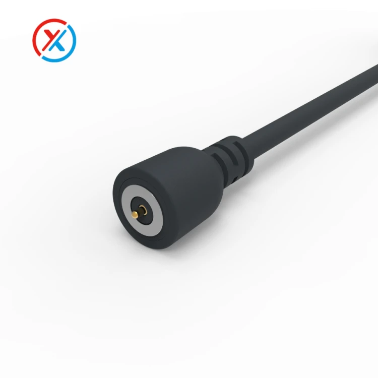

Another key part of the puzzle is how the pogo pin is integrated into the final assembly, whether that’s a cable or a component. That’s why we often work with clients on our Usb Pogo Pin Cable line, because the cable itself is a big part of the impedance chain. Even the best pogo pin will have issues if the cable attached to it has a different impedance. We offer custom-cable assemblies where we match the cable’s impedance to the pogo pin, whether it’s the 50 ohm standard for power or 90 ohm for data. For applications that need a more flexible connection, like magnetic cables, we also align our pogo pin specs with magnetic connector standards—our range includes Charging Cable Magnetic Connector and Round Magnetic Cable Connector options that pair seamlessly with our pogo pins, because we account for the connector’s impedance too. It’s not just the pin alone; it’s the entire signal path from the source device, through the pogo pin, cable, and mating connector, to the target device that needs to match.
Let’s talk about a real example we worked on last year. A client who makes ruggedized portable speakers came to us. They were using standard pogo pins for charging and data transfer, but after designing the product, they found that when transferring large audio files to the speaker, the transfer would fail after a few seconds. Their initial testing showed that the pins were mechanically sound, so they suspected an electrical issue. We tested their setup and found that their pogo pins had an impedance of 105 ohms, while their cable was rated for 90 ohms. The mismatch was causing signal reflections that disrupted the high-speed data transfer. We worked with them to adjust our pogo pin design to hit 90 ohms, matched our Usb Pogo Pin Cable to that impedance, and paired it with one of our reliable Magnetic Cable Connector ends for easy, tool-free connection. After making that change, their data transfers became rock-solid, and they haven’t had a single report of connectivity issues since. That’s the value of getting impedance matching right—it’s not just a technical detail, it directly impacts a product’s real-world performance.
Common mistakes we see designers make when working with USB pogo pins include assuming all pogo pins are the same (they’re not—size, material, and design all change impedance), not considering the entire assembly (the pin, cable, and connector all matter), and cutting corners on testing. Some designers use off-the-shelf pogo pins that aren’t spec’d for high-frequency signals, which works for low-speed applications like basic charging, but fails when data is involved. Others pick a cable based on length or cost alone, not realizing that the cable’s impedance will throw off the whole system. We always recommend that clients work with their connector supplier early in the design process, not after they’ve already built a prototype. That way, we can tailor the pogo pin, cable, and connector to match their specific USB standard (USB 2.0, USB 3.x, USB-C) and application, avoiding costly redesigns later.
What about for lower-power applications, like wearables that use USB for charging but not high-speed data? Impedance is still important, though the tolerance can be a bit wider. Even here, a mismatch can cause voltage drops that make charging slower, or cause the connection to drop when the wearable is moved. That’s why we have options like the Pogo Pin Cable Diameter 8.0mm, which is robust enough for frequent use and has an impedance tuned for low-power USB charging, so you don’t have to worry about slow top-ups when your smartwatch needs a quick charge.
At the end of the day, USB pogo pin impedance matching is about creating a seamless, efficient connection where signals and power flow smoothly from one device to another. It’s a balance of mechanical design, material science, and testing that ensures the pogo pin works as part of a larger system, not just a standalone component. For us, as a supplier, our job isn’t just to sell pins—it’s to work with designers to solve their connectivity challenges, whether that’s high-speed data transfer, high-power charging, or rugged, reliable connections for industrial or consumer products.
If you’re working on a new project and want to make sure your USB pogo pin setup has the right impedance, or if you’ve been dealing with connectivity issues and suspect an impedance mismatch is to blame, we’re here to help. Our engineering team can walk you through the best pin, cable, and connector options, whether you need a custom solution tailored to your exact specs or a standard component that’s already proven to perform. We’ve partnered with countless clients across industries, from consumer electronics to medical devices, to get their USB connections right—don’t let a small technical detail like impedance slow down your product launch or cause frustrating performance issues for your customers.
Reach out to our team to discuss your USB pogo pin needs, and we’ll help you find the perfect components for your application, with the right impedance, durability, and performance you can count on.
References
- Johnson, H., & Graham, M. (2003). High-Speed Signal Integrity. Prentice Hall.
- USB Implementers Forum. (2022). USB-C Cable and Connector Specification, Release 2.2.
- Pina, J. (2019). Spring-Loaded Connectors: Design, Materials, and Applications. IEEE Transactions on Components, Packaging, and Manufacturing Technology.
- Texas Instruments. (2021). Impedance Matching for High-Speed USB Systems. Application Note SLVA872.