If you’ve ever dug into the technical specs of connectors for consumer electronics, automotive sensors, or medical devices, you’ve probably stumbled across the term “pitch” when talking about pogo pins. As a pogo pin supplier who’s spent years troubleshooting and customizing these tiny springs for clients ranging from smartphone manufacturers to defense contractors, I get more questions about pogo pin pitch than any other technical detail. Most people start with a basic definition, but very few dig into why this measurement matters—beyond just fitting parts on a circuit board. Let’s break this down, straight from someone who works with these pins every day.
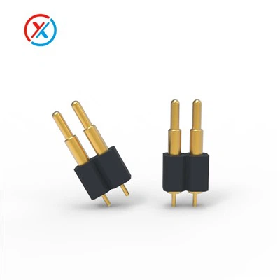
First, let’s get the fundamentals right: pitch refers to the center-to-center distance between two adjacent pogo pins in an array. It’s measured in millimeters (mm) almost exclusively for modern electronics, and it’s one of the most non-negotiable specs when designing a connector. Too narrow a pitch, and you risk short circuits from pin-to-pin arcing, solder bridging, or debris getting trapped between pins. Too wide, and you waste valuable board space that’s at a premium in everything from smartwatches to EV battery management systems.
I learned this lesson early on when I was helping a client who builds wireless earbud charging cases. They initially used a standard 1.2mm pitch pogo pin array, but their new, slimmer case design only had 0.8mm of linear space for the connector. At first, their engineering team thought they could just shrink the pins to fit, but that’s not how pitch works. The core components of a pogo pin— the barrel, spring, plunger, and contact point—have a minimum size limit based on material strength. Shrink those parts too much, and the spring loses tension, so it can’t consistently make contact with the charging port’s pads. That’s where custom design comes in, and it’s why clients come to a reputable pogo pin supplier instead of trying to source generic parts.
Let’s talk about the most common pogo pin pitches you’ll encounter, because not all pitches are created equal, and choosing the wrong one can derail an entire product launch. The smallest standard pitch we offer is 0.3mm, which is used exclusively in ultra-compact devices like wearables and medical diagnostic tools. I recently supplied a batch of Pogo Contacts 1mm wait, no, wait—let’s correct that: our 0.3mm pitch pins are the smallest in our lineup, used for things like hearing aids, where every millimeter of space counts. Because the pins are so close together, we always specify gold-plated pogo pins here, as the gold coating prevents corrosion and reduces electrical resistance even on tiny contact points.
Next up is 0.5mm and 0.6mm pitch, which is the sweet spot for mid-sized consumer electronics: things like Bluetooth speakers, tablet docks, and laptop peripheral connectors. This range balances density with reliability—enough space for the pins to move freely without arcing, but compact enough to avoid wasting board space. I see a lot of clients default to these pitches when they don’t have tight space constraints, and they work for most low-to-medium current applications. For higher-current use cases, though, you need a slightly wider pitch to accommodate the larger contact area needed to carry power. That’s where 0.8mm to 1.0mm pitch comes in, used for EV battery sensors, power banks, and industrial control panels. When dealing with higher currents, a wider pitch also helps with heat dissipation—smaller, closely spaced pins trap heat, which can degrade the spring over time and cause contact failure.
The largest standard pitch we offer is 2.54mm, which is the familiar 0.1” pitch used in breadboards and prototyping. This is mostly for hobbyist projects and low-volume industrial testing fixtures, where size isn’t a critical constraint, and easy manual alignment is a priority.
Now, here’s where things get nuanced: pitch isn’t a one-size-fits-all number, and there are a lot of factors that go into choosing the right one for your application. Let’s walk through a few of the most important ones.


First, electrical current. As I mentioned earlier, higher current requires a larger contact area. If you use a 0.5mm pitch pin for a 5A power connection, the tiny contact point can overheat, leading to voltage drop and even permanent damage. A 1.5mm pitch pin, on the other hand, has a larger plunger and contact tip, so it can handle that same current with less resistance and heat buildup. That’s why we always work with clients to calculate their current load before recommending a pitch—we don’t just sell generic pins; we build solutions that work for their specific needs.
Second, board space. This is obvious, but it’s the biggest driver for custom pitches. When a client is shrinking their product by 20% to fit into a new form factor, their old 1.0mm pitch just won’t work. We recently worked with a smartphone client that was designing a foldable phone with a flexible display module. The connector between the display and the main logic board only had 0.7mm of space for 8 power and data pins. Off-the-shelf pins wouldn’t fit here without overlapping, so we engineered custom 0.7mm pitch pins with a flattened plunger design to avoid short circuits, all while meeting the required current rating for high-speed display data. For these custom jobs, we also rely on advanced plating techniques, like the gold plating offered in our Gold Plated Pogo Pins lineup, which ensures consistent contact even when pins are packed tightly together.
Third, environmental conditions. If your pogo pins are going to be used in a high-vibration setting—like a construction vehicle sensor or a medical implant—you need a wider pitch to reduce the risk of pins bouncing or making unintended contact. Moisture, dust, and temperature extremes also play a role. In outdoor industrial equipment, for example, a 2.0mm pitch is often used because it leaves more space for seals, preventing contaminants from getting between pins and causing corrosion. For lead-free applications, which are required for many consumer electronics to meet global regulatory standards, we offer Lead-Free Pogo Pin options that are calibrated to perform at standard pitches without sacrificing reliability.
Fourth, assembly method. SMT (surface mount technology) pogo pins, which are soldered directly to a PCB, require precise pitch alignment. If you’re hand-assembling a small batch of prototypes, a wider pitch like 2.54mm is much easier to work with, as you can align pins by eye. For high-volume automated assembly, even smaller pitches like 0.5mm are manageable, as long as the pins have consistent, repeatable dimensions that automated pick-and-place machines can handle. That’s why we invest in precision manufacturing equipment—our pins have a tolerance of ±0.02mm for pitch, which is critical for automated assembly lines that process tens of thousands of parts an hour.
A common misconception I hear from new engineers is that a smaller pitch is always better, because it saves space. But that’s only true if it doesn’t compromise performance. I once had a client come to us with a prototype for a wearable heart monitor that used 0.2mm pitch pins, thinking it would make their device smaller. But when they tested it, they saw a 30% failure rate because of short circuits between closely spaced pins and insufficient spring tension. We had to redesign the connector to a 0.4mm pitch, which added a tiny bit of board space but brought the failure rate down to less than 0.1%. That’s the tradeoff: pitch is a balance of size, performance, reliability, and cost.
Now, let’s talk about how to confirm the pitch of a pogo pin array if you’re working with parts you already have. The easiest way is to count the number of pins in a linear array and measure the total width of the array between the outer edges of the two end pins. For example, if you have 5 pins in a straight line that measure 4mm total, the pitch is 1mm, because there are 4 gaps between 5 pins (4mm divided by 4 gaps = 1mm pitch). This works for linear arrays, which are the most common, but for staggered arrays (where pins are offset in two rows), you’ll need to measure both the horizontal and vertical center distances between adjacent pins, as they might not be the same.
If you’re in the market for pogo pins and you’re trying to figure out what pitch you need, the best first step is to reach out to a reputable Pogo Pin Supplier who can guide you through the process. Don’t just look for the cheapest pins—ask about their manufacturing tolerances, plating options, and experience with your specific application. For example, if you’re building a PCB that uses pogo pins, check our Pogo Pins PCB page to see how our pins are designed to interface with standard PCB footprints, which can save you a ton of time on prototyping and assembly.
If you’re still stuck, think about the end use case: what’s the device’s size? How much current does it need to carry? Will it be exposed to harsh conditions? Once you answer those questions, you can narrow down your pitch range, and a good supplier will help you refine it further.
At the end of the day, pitch is more than just a number on a spec sheet. It’s the foundation of reliable pogo pin performance, impacting everything from how small your product can get to how long it will last. Over my 10 years as a pogo pin supplier, I’ve seen projects launch successfully because they got their pitch right, and fail because they picked the wrong one. That’s why we take the time to work with each client, digging into their needs beyond the basic specs, to deliver pins that work as hard as their products do.
If you’re designing a new product, troubleshooting a faulty connector, or just have questions about pogo pin pitch for your next project, don’t hesitate to reach out to our team. We can walk you through our standard and custom pitch options, help you select the right design for your application, and provide samples to test before you commit to a full order.
References
- "Pogo Pin Design Guidelines and Technical Specifications". Pogo Pin Industry Journal, 2022.
- "Pitch Selection for Surface Mount Pogo Pins". Electronic Components and Technology Conference (ECTC) Proceedings, 2021.
- "Materials and Plating for High-Reliability Pogo Pin Applications". Journal of Microelectronics and Electronic Packaging, 2020.
- "Regulatory Requirements for Lead-Free Electronic Components". International Electrotechnical Commission (IEC) Report, 2023.