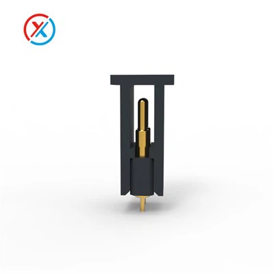
If you’ve ever taken apart a smartphone, a wireless earbud case, or a foldable tablet, you’ve probably seen them: tiny, spring-loaded metal pins that make invisible connections between moving parts or charge devices without bulky cords. These parts, known as pogopins, are the unsung heroes of modern mobile design, and their installation isn’t just a matter of shoving them into a circuit board. For mobile devices, where every millimeter counts and reliability is non-negotiable, getting the installation right can mean the difference between a device that lasts two years and one that survives a decade of daily use. As a pogo pin supplier who’s worked with engineers across the mobile industry for over a decade, I’ve seen firsthand how even a small misstep in installation requirements can derail a product launch or lead to costly post-market repairs.
Pogopins are designed to do two core jobs in mobile: transmit data (like syncing an earbud to a phone) and carry power (like charging a smartwatch wirelessly or connecting a foldable display’s hinge). Unlike traditional soldered wires, they use a spring-loaded mechanism to create a continuous connection, even when parts shift—something critical for devices that bend, fold, or are rubbed against. To work correctly, though, their installation has to account for three key variables: mechanical fit, electrical performance, and durability in the harsh environment of a mobile device.


First, mechanical installation is non-negotiable. When we talk about pogopins for mobile, you’ll often hear them called spring loaded pins, and their physical placement has to hit a narrow sweet spot. The first rule here is the insertion depth: too shallow, and the spring can’t compress enough to make solid contact; too deep, and you’ll crush the spring over time, leading to weak or failed connections. For most mobile applications, that depth is between 0.2mm and 0.5mm—enough to keep the spring engaged during normal use but not so much that it wears out prematurely. I’ve seen engineers cut corners here, only to have devices fail within weeks as the spring loses its tension.
Next is the hole size where the pin is mounted. Mobile circuit boards are tiny, so even a 0.1mm difference can cause big problems. If the hole is too small, the pin won’t slide in, and forcing it will bend the delicate contact tip. If it’s too big, the pin will wobble, leading to inconsistent connections. For surface-mount (SMT) pogopins, which are the most common in mobile, the hole diameter should be 0.05mm to 0.1mm larger than the pin’s shank. That gives enough room for easy installation without sacrificing stability. I always recommend checking the pin’s datasheet—each manufacturer’s pins have slightly different specs, and as a pogo pin supplier, we provide detailed installation guides tailored to every product we make.
Alignment is another mechanical factor. In mobile devices like foldable phones, pogopins connect the main board to the hinge or secondary display, which moves every time you open or close the device. If two mating pins are even 0.1mm out of alignment, the spring will tilt instead of compressing straight, wearing down the inner wall and causing early failure. Many engineers use alignment sleeves or positioning fixtures during installation to avoid this, but for high-volume production, automated pick-and-place machines are calibrated to precision to make sure every pin lines up perfectly.
Moving past mechanical fit, electrical installation requirements are equally important. Pogopins carry current, so their contact surface has to be clean and properly attached to the circuit. A common mistake is using too much solder when mounting the pin to the board. Too much solder can seep up the pin’s shaft, block the spring’s movement, or create a short circuit between adjacent pins. Solder should only cover the base flange of the pin and a small portion of the board pad—no higher than 0.1mm up the pin. We also recommend using lead-free solder, which is required for most mobile devices to meet global environmental standards, as it has the right melting point for SMT processes without damaging the board’s delicate traces.
Contact resistance is another electrical criticality. A pogopin’s job is to create a low-resistance path between two components, so any barrier between the pin’s tip and the mating pad will cause voltage drops or data errors. That means the mating surfaces (the pin’s tip and the receiving pad) have to be free of oxidation or flux residue. After installation, we recommend a quick cleaning with isopropyl alcohol to remove any flux left over from soldering—even a thin layer of residue can increase resistance by 20% or more, which can make a wireless charger work slowly or cause data sync failures. For devices that will be used in humid environments, many engineers choose gold-plated contact tips, which resist oxidation better than tin or nickel. As a pogo pin supplier, we offer multiple plating options, and we always advise pairing the pin’s plating with the mating pad’s to ensure the lowest possible resistance over time.
Durability is the third big installation requirement for mobile devices, and it’s often the most overlooked. Mobile devices are dropped, rubbed, and exposed to temperature swings, so pogopins have to handle repeated stress without failing. The first factor here is the force the pin exerts on the mating pad. Too little force, and the connection will be inconsistent when the device is jostled; too much force, and the pad on the receiving component will lift off the board, or the pin’s spring will wear out quickly. For most mobile applications, the optimal contact force is between 50 grams and 100 grams per pin. We test every batch of our pogopins to make sure they stay within this range, but installation can throw this off: if the pin is mounted too tightly, the spring can’t reach its full tension, so the contact force will be lower than designed, leading to intermittent connections. If it’s too loose, the pin will move around, and repeated movement will break the solder joint.
Temperature cycling is another durability test that installation affects. Mobile devices go from a warm pocket to a cold car, and each cycle causes the circuit board and the pin’s metal to expand and contract at different rates. If the pin’s base isn’t properly bonded to the board, the solder joint will crack over time. To prevent this, many engineers use a thermal adhesive under the pin’s flange to fill gaps between the pin and the board, which absorbs some of the stress from temperature changes. For high-vibration applications, like ruggedized mobile devices, we also recommend double-ended pogopins, which connect two boards at once without relying on a single spring, reducing the risk of failure from repeated movement.
I’ve heard a lot of myths about installing pogopins over the years—some engineers think you just push them in and solder, and they’ll work forever. But I’ve seen devices where a single misaligned pin led to a $100,000 production line shutdown, or where excessive solder caused a batch of wireless earbuds to fail in 30 days. That’s why at our company, we don’t just sell pogopins; we work with engineers through the design and installation process to make sure every step meets mobile-specific requirements.
For example, when a major smartphone maker came to us a few years ago with a foldable phone design, they were struggling with pogopins that failed after 1,000 folds—less than the industry standard of 10,000. We tested their installation process and found that the pins were being mounted too shallow, so the spring only compressed half as much as designed. By adjusting the insertion depth and recommending a specific alignment fixture, we helped them increase the fold life to over 15,000, which was enough to get their product to market on time. That’s the kind of support a good pogo pin supplier provides—not just a product, but solutions for real design challenges.
Now, if you’re an engineer working on a mobile device, or a procurement manager looking for reliable pogopins, you might be wondering where to start. The first step is understanding your specific application: is this a wireless charger, a data sync connector, or a hinge connection? Each has slightly different requirements, and the wrong pin or installation method can cost you later.
I always recommend doing your research on reputable suppliers, and as a company that focuses on mobile applications, we have a range of options to suit different needs. If you’re looking for standard single-ended pins, check out our Pogopin page for detailed specs, or if you need right-angle pins for tight spaces, head to Buy Pogo Pins to browse our SMT and through-hole options. For foldable or hinge applications, our Double-ended Pogopins are designed to handle repeated movement, and if you want to dive deeper into spring mechanics, the Spring Loaded Pins page has installation guides and test data tailored to mobile devices.
But beyond just picking a product, make sure you’re following installation best practices. Don’t cut corners on alignment, don’t use too much solder, and test your assembly under real-world conditions—temperature cycles, vibration, and repeated movement. A few extra steps during installation can save you months of headaches later.
At the end of the day, pogopins are small parts, but they play a huge role in mobile device functionality. For engineers and manufacturers, getting their installation right isn’t just about following specs—it’s about building a product that people can rely on, day in and day out. If you’re working on a new device and need help with pogopin design, installation, or sourcing, our team is here to answer your questions and provide guidance tailored to your needs. Don’t hesitate to reach out to our team to discuss your requirements, and let’s make sure your next device’s connections are as reliable as the rest of its design.
References:
- International Electrotechnical Commission (IEC) 60512-11-3: Connectors for electronic equipment - Tests and measurements - Part 11-3: Mechanical tests on contact elements and contact assemblies - Test 11c: Mating and unmating durability.
- Mobile Industry Processor Interface (MIPI) Alliance. MIPI Alliance Design Guidelines for Interconnect Solutions in Mobile Devices, 2022.
- NXP Semiconductors. “Pogo Pin Application Note: Best Practices for Mobile Charging and Data Connectors,” 2021.
- IPC-A-610: Acceptability of Electronic Assemblies, International Printed Circuit Board Association, 2023.
- Samsung Advanced Institute of Technology. “Mechanical Reliability of Interconnects for Foldable Mobile Displays,” Journal of Microelectronics and Electronic Packaging, Vol. 18, No. 2, 2021, pp. 45-52.