

Electrical Characteristics: What Can the Connector Carry?
Current and temperature rise. Continuous current is the load a connector can carry over time under specified conditions. A peak current also needs a duration and repetition rate. A motor that draws a brief surge once at startup places a different thermal load on its connector from one that restarts every few seconds. When comparing current ratings, check the ambient temperature, wire gauge or PCB copper layout, and number of adjacent contacts carrying current. These conditions affect how readily heat can leave the terminals.
Contact resistance and voltage drop. Suppose a mated power connection measures 10 mΩ between two voltage-sensing points. At 5 A, the voltage drop across that section is 50 mV, and it dissipates 0.25 W. Where that heat develops depends on what lies between the sensing points. A measurement taken on the metal terminals immediately behind the mating interface covers a shorter path than one taken on the wires behind both crimps. For low resistance, use a four-wire measurement and identify the sensing points on the drawing. To find how much voltage the device actually receives, include the return path as well.
Working voltage and insulation. Rated voltage describes the intended operating limit under the stated conditions. Insulation resistance measures how strongly separated conductors resist leakage at a specified test voltage. Dielectric withstand voltage is the higher voltage applied for a defined test interval to check whether the insulation breaks down. Use the working-voltage rating when selecting a connector for continuous service.
High-speed signals. An impedance change at the connector can reflect part of a signal. Insertion loss describes attenuation through the measured path, while crosstalk describes unwanted coupling from a neighboring channel. For a board-to-board link, read the curves over the frequency range specified for the interface. Check the mated height, signal and ground pin assignments, and whether the measurement includes the PCB launches. Two connectors with the same pitch can behave differently at the target data rate.
Mechanical Characteristics: Will the Contacts Stay Engaged?
Insertion force tells the assembler how hard it is to mate a plug and socket. Withdrawal force describes the effort needed to separate the pair under the stated latch condition. Terminal retention concerns a different failure: an individual terminal backing out of its housing. If a wire pulls free while its terminal stays seated, the relevant measurement is the wire-to-terminal crimp pull force.
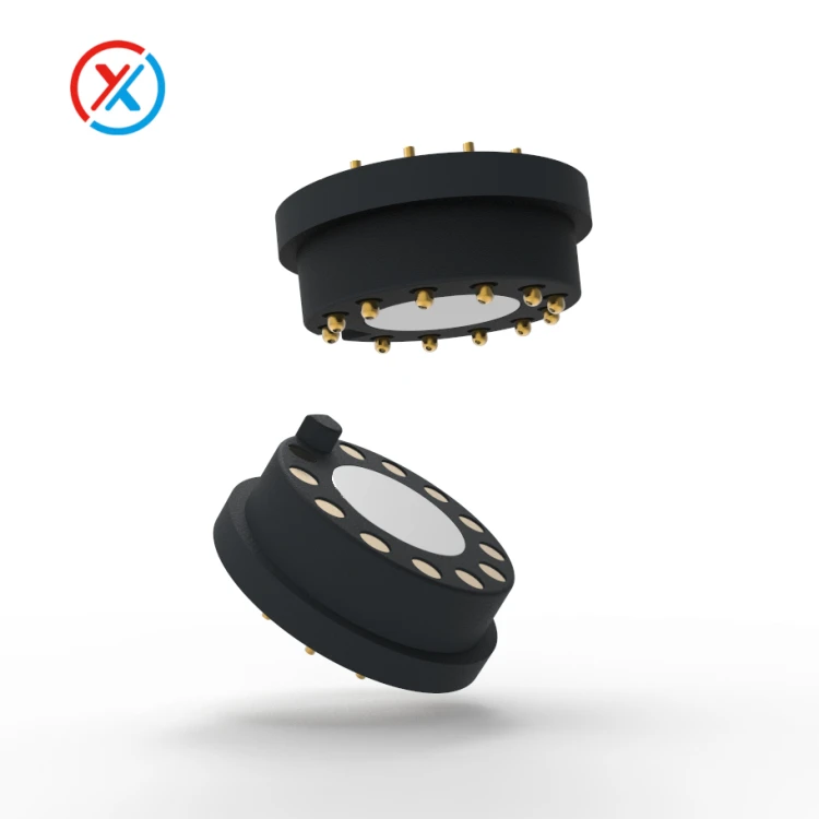
A pogo pin charging dock depends on contact force at the installed height. At the largest assembly gap, the shortest pin must still press firmly enough against its pad. At the smallest gap, the tallest pin needs travel left within its specified working range. For a multi-pin connector, add the spring forces at their actual compression positions and check whether the latch or magnets can hold the dock fully closed.
A mating-life figure also needs context. Look for the mating part, contact finish, stroke, cycle count, and whether current flowed as the contacts made or broke. Compare resistance, mating or spring force, and plating wear before and after cycling. A dock may still close normally after thousands of cycles even though the voltage drop across a worn contact has increased.
Environmental Characteristics: What Changes in Service?
| Condition | What to check in the product |
|---|---|
| Temperature | Measure local ambient temperature beside the connector and terminal temperature under sustained load. Their difference is the temperature rise. A connector beside a battery or power converter may start well above room temperature. The storage range applies to the unpowered part. |
| Moisture, dust, and contamination | Identify the state covered by the ingress rating. A rating may apply to a mated pair, a capped receptacle, or a complete panel installation with a specified seal and cable diameter. For exposed charging pads, also check contact resistance after the expected exposure to sweat or residue. |
| Vibration and shock | Monitor continuity during motion and record the shortest interruption the equipment can detect. Then inspect the latch, terminal position, and mounting hardware. A loose contact can interrupt power during vibration and pass a static continuity check afterward. |
Which Specifications Matter Most for Each Connector Type?
| Connector and application | Specifications to check first | Question that determines suitability |
|---|---|---|
| Wire-to-board power connector | Current per terminal, temperature rise, wire gauge, crimp pull force | Which terminal runs hottest when all intended circuits carry their operating current? |
| High-speed board-to-board connector | Impedance, insertion loss, crosstalk, mated height | Do the published curves cover the required frequency range and the stack height used in the product? |
| Pogo pin charging connector | Working height, force at that height, contact resistance, mating life | At the largest housing gap, can the dock maintain charging voltage after repeated use? |
| Outdoor circular connector | Sealing configuration, locking method, cable diameter range, vibration performance | Does the complete cable and panel assembly maintain its seal and stay locked in service? |
How to Read a Connector Datasheet: A Worked Example
Part 811-22-002-30-002101 is a two-position, surface-mount spring-loaded header with round tips on a 2.54 mm pitch. Its July 2025 datasheet gives a nominal free height of 5.004 mm and a stroke of 1.397 mm. The following design example assumes two gold-plated mating pads, a mounting-plane-to-pad gap of 4.20–4.40 mm, a continuous charge current of 1 A, and a service target of 10,000 docking cycles. These are illustrative dock requirements.
Start with the widest gap. At 4.40 mm, nominal pin compression is about 0.60 mm. At 4.20 mm, it is about 0.80 mm. The design therefore operates on either side of the nominal mid-stroke position of 0.70 mm. That makes the header worth sampling. The remaining question is how much force the shortest assembled pin delivers at the widest gap, particularly if the device can tilt in the dock.
Follow the complete charging path. With one pin supplying power and the other carrying the return, both carry the full 1 A. Measure the drop from each header termination to its corresponding device-side pad and add the two readings. If the dock allows 50 mV across this interface at 1 A, the two paths together have a 50 mΩ resistance budget. Measure the hottest terminal after its temperature stabilizes in the closed dock.
| Check | Published value or supplier test condition | Dock measurement and acceptance decision |
|---|---|---|
| Contact at both gap limits | The part drawing gives 5.004 mm free height and 1.397 mm total stroke. | Calculated nominal compression is 0.60–0.80 mm. Confirm tip position, minimum contact force, and remaining travel on assembled samples at both gap limits. |
| Voltage drop and temperature | The supplier's contact-family report tested three contacts individually at half stroke against a gold-plated target. A thermocouple measured plunger temperature. | Measure both paths while charging at 1 A in the enclosure. Acceptance requires a combined drop within the example's 50 mV budget and a hottest-terminal temperature within the product limit. |
| Performance after repeated docking | The part datasheet lists 100,000 to 1,000,000 mechanical cycles at mid-stroke. | After the dock's 10,000-cycle target, repeat the force, voltage-drop, and thermal checks at the same locations. Inspect both mating pads for wear. |
The published dimensions support a sample evaluation. Production approval requires measurements from the assembled dock. Its qualification record should identify the drawing revision, pad finish, number of samples, sense and temperature measurement locations, and reviewing engineer. If a standard pin falls short at either gap limit, those measurements also give Dongguan Xinteng Electronics Co., Ltd. a concrete starting point for reviewing a different spring force or free height against the customer's drawing.
Technical References
Product Number 811-22-002-30-002101 Data Sheet. Updated July 21, 2025. Mechanical drawing and product specifications, pages 1–2.
Spring Loaded Contact: Specifications, Mechanical & Climatic Tests. Version 2.0, October 2005. Mechanical cycling and current-carrying capacity test methods and results.


