



Soldering Pogo Pins
Your Professional Soldering Pogo Pins Supplier
Dongguan Xinteng Electronics Co., Ltd. is a leading high-reliability Pogo Pin connector solution provider in China, integrating R&D, production and sales.
The main solutions include: Pogo pin connector solutions, magnetic connector solutions, pogo pin cable solutions, precision accessories, etc.


soldering pogo pins
Through-hole spring contacts, soldered once and mated thousands of times.
What are soldering pogo pins?
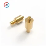
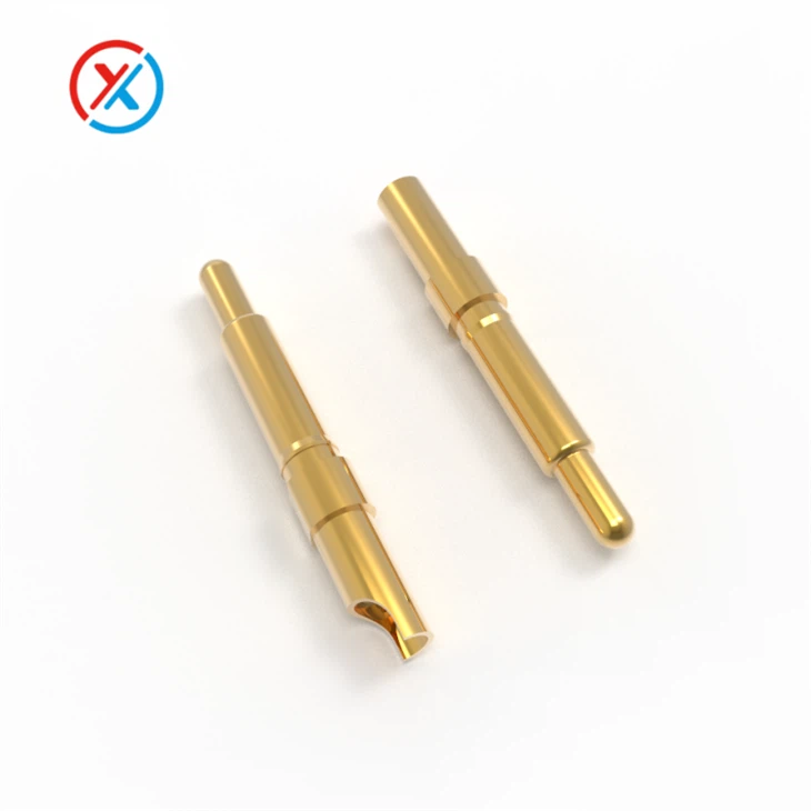
A soldering pogo pin's own tail is built for solder termination: wave-soldered or hand-soldered through a plated hole in the PCB, rather than surface-mounted or press-fit. Once that joint is made, the spring-loaded tip on the other end does the opposite job. It's designed to be mated and unmated thousands of times without ever touching a soldering iron again.
That split is the whole point of the part. One end trades flexibility for a permanent, high-strength joint. The other trades permanence for reusability, which is why this category shows up in test fixtures, battery contacts, and anywhere else a connection needs to be made and broken without redoing the solder work each time.
Why Choose us
Quality Assurance
Our products comply with the EU RoHS, REACH, and HF environmental standards, and we have accumulated extensive experience in the fields of pogo pins and pogo pin charging cables.
Comprehensive Patent Portfolio
We offer more than 2000 tailored solutions to customers and have obtained over 100 product patents.
Customization Services
We provide personalized customization services to meet the specific requirements of diverse application scenarios.
Representative specifications
The table below is for the RG-1122, our highest-current soldering pogo pin, not the typical one in this range. For the signal-level end of the lineup, see Soldering Pogo Pins DC 3A above.
|
Product model |
RG-1122 |
|
Mechanical |
|
|
Life test |
20,000 cycles |
|
Electrical |
|
|
Rated voltage |
DC 12V |
|
Rated current |
30A Max |
|
Contact resistance of spring pin |
20 Milliohm Max |
|
Environmental performance |
|
|
Operation Temperature |
-25℃ to +85℃ |
|
Salt Spray |
48H |
|
Packing |
PE bag / reel packing |
|
Material and coating conform to ROHS and REACH standards |
|
Two things worth knowing while the fields above are pending: across the catalog, spring force generally runs 50–500 gf depending on configuration, so the exact number for RG-1122 will fall somewhere in that band once confirmed, not outside it. Separately, the 30A / 20 mΩ combination implies real heat at full load; the FAQ below covers how barrel thickness and contact resistance need to scale together at this current level, and that resistance figure is worth re-verifying for this specific configuration rather than treated as fixed across the lineup.
How it works

PCBSolder joint (through-hole)Plunger, reusable, no solderSpring + barrelWave or hand soldered, permanent
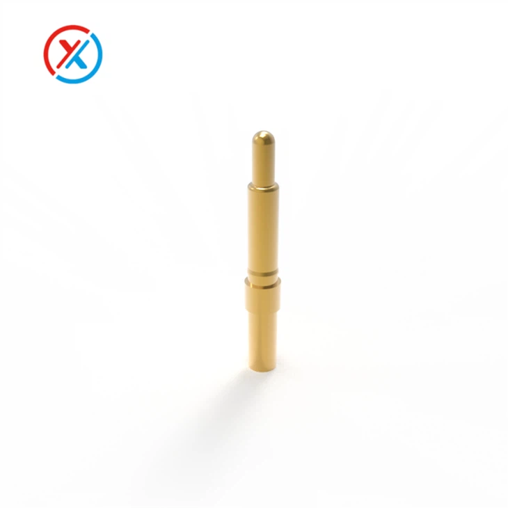
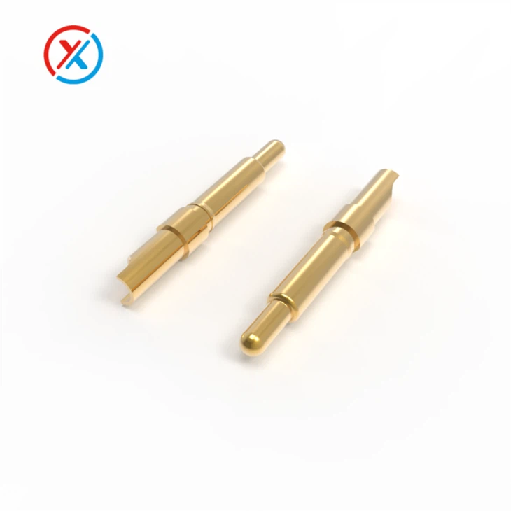
The tail passes through a plated hole and is soldered from the underside, the same way a header pin or DIP component would be. It's rated for the same solder temperatures as the rest of the through-hole assembly. The plunger on top does the reusable part of the job: repeated mating cycles, no soldering iron involved after the initial install.
Benefits

High-density layout
Suitable for compact designs. Saves board space and assembly height compared to bulkier connector styles, which matters as devices get smaller and more integrated.
Reliable under repeated cycling
Mature spring and barrel design keeps contact stable through repeated mate and unmate cycles. The RG-1122 above is rated for 20,000 cycles; see the FAQ for how that number changes with contact force and plating choice.
Low contact resistance
Blind-hole electroplating on the contact surface keeps resistance low, which matters for signal integrity and, at higher current ratings, for how much heat the contact generates under load.
Strong durability
Material selection and precise tolerancing keep the connection stable even in harsher working environments over the long term.
Applications of Soldering Pogo Pins
Electronics testing
Used in bed-of-nails test fixtures to check circuit boards quickly and reliably, standing up to repeated contact without wearing out the board under test.
Battery Connections
Common for battery contacts in portable devices like smartphones and handheld scanners. The result is a stable, low-resistance connection that also allows easy battery replacement.
PCB Interconnects
In modular systems, lets boards be assembled and disassembled without re-soldering each connection. The pin itself is the only thing that was ever soldered; everything it mates with afterward is solder-free.
Precautions
- Design the working compression to land around two-thirds of the total stroke. Too little compression means too little contact force, and resistance becomes inconsistent. Too much compression pushes the plunger past its limit, which can damage the barrel opening and cause the pin to stick.
- During assembly, keep lateral force off the barrel opening. A sideways knock is the more common cause of a stuck or jammed pin, not straight-down pressure.
- Keep battery contacts and any mating FPC gold fingers free of dirt, oxidation, or residue. Contamination at the contact surface causes more field failures than worn-out pins do.
Quality & testing
Every batch goes through 100% spring-force inspection before it ships. Each pin is checked at its rated working stroke, not sampled. Contact resistance is measured with a four-wire Kelvin setup, the only reliable way to get a clean reading on a component this small. Plating and base materials are checked against RoHS and REACH limits before a job is approved for production, and the factory is ISO 9001 certified, with ISO 13485 for medical-grade quality management currently in process.
Standard hard gold plating runs 0.3 to 1.0 μm cobalt-hardened gold over 2 to 5 μm electroless nickel. Spring force across the catalog spans roughly 50 to 500 gf depending on configuration, so a light-touch signal contact and a heavy-duty high-current pin aren't built to the same tolerance by accident; they're different parts of the same range.
Because this category's tail is soldered rather than surface-mounted, every batch also gets a solderability check: dipping a sample and confirming even wetting across the pre-plated surface before it ships. A tail that looks fine but solders poorly is the most common cause of a cold joint in the field, which is also why it's worth asking any supplier about this specific test (see FAQ below).
Standard MOQ starts at 5500 pieces. Custom configurations typically ship in 5 to 15 days once a drawing is confirmed, against a roughly 7 to 25 day range that's common elsewhere in the industry for comparable custom tooling.
Shipping & payment
|
Shipping |
Sea freight, air freight, or express courier, depending on order size and destination. |
| Payment terms | T/T, L/C, PayPal, and credit card are standard; other terms negotiable on request. |
FAQ