



Right Angle Pogo Pin
Your Professional Right Angle Pogo Pin Supplier
Dongguan Xinteng Electronics Co., Ltd. is a leading high-reliability Pogo Pin connector solution provider in China, integrating R&D, production and sales.
The main solutions include: Pogo pin connector solutions, magnetic connector solutions, pogo pin cable solutions, precision accessories, etc.


Right Angle Pogo Pin
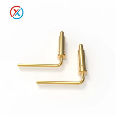
90° spring-loaded contacts for board edges and low-clearance mounting.
A right angle pogo pin bends the contact path 90 degrees: the barrel mounts flat on the PCB, but the plunger extends and retracts horizontally instead of straight up. That matters anywhere vertical clearance is the limiting factor — a thin bezel, a stacked board assembly, or a test fixture where the mating surface sits to the side rather than above the board.
Below: which variant actually fits your application, a representative spec sheet, and the mounting and reliability details that matter once you're past the datasheet stage.
Representative specifications
Full parameters differ by model. The table below is for the RG 1100, our standard right-angle reference part, so you have one concrete data point. For a different current or stroke requirement, see the FAQ below or ask us directly for the datasheet that fits your application.
|
Product model |
RG 1100 |
|
Mechanical |
|
|
Contact force |
80g士20g at 0.5mm working storke Full storke 0.7mm |
|
Life test |
20,000 Cycles |
|
Electrical |
|
|
Rated voltage |
DC 12V |
|
Rated current |
1A Max |
|
Contact resistance of spring pin |
50 Milliohm Max |
|
Environmental performance |
|
|
Operation Temperature |
-25℃ to +60℃ |
|
Salt Spray |
48H |
|
Packing |
PE bag / reel packing |
|
Material and coating conform to ROHS and REACH standards |
|
On the 1A rating: RG 1100 is a signal/low-power contact, not a charging-current part. If your application is battery testing or charging rather than signal or control lines, see the FAQ below or check High Current Pogo Pins for the right amperage class.
Products Description
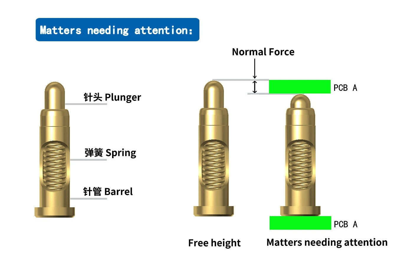
The barrel solders flat onto the PCB pad and goes through reflow like any other SMT part. Instead of the spring pushing the plunger straight up, a right-angle housing redirects that same spring force sideways, so the plunger travels parallel to the board rather than away from it. Everything else about the contact — spring compression, wipe on mating, resistance under load — works the same way it does in a straight pogo pin. Only the direction of travel changes.
For the RG 1100 above, that's a 0.5mm working stroke out of 0.7mm full travel: a 0.2mm margin before the spring bottoms out, same logic as any pogo pin — push past full stroke in the mated position and the spring takes a permanent set, reducing contact force on every cycle after.
Benefits of Right Angle Pogo Pin
Contact happens horizontally instead of vertically, which matters directly in height-restricted designs — mobile devices, portable electronics, compact test fixtures — where every millimeter of stack height is accounted for.
The 90° orientation of the pin gives a designer placement options that a straight pogo pin can't — routing a contact along an edge or into a corner that a vertical stack would never reach.
Because mating force is applied horizontally rather than pressing straight down into the board, there's typically less stress transmitted through the PCB during mating and unmating — a real consideration on thin or delicate boards.
Right-angle pins are common in SMT assemblies precisely because the horizontal orientation makes it easier to hold accurate alignment with a mating surface positioned near the board edge.
Horizontal placement fits standard pick-and-place and reflow workflows without special fixturing, which keeps assembly cost and complexity down compared to connectors that need a separate mounting step.
Manufacturing & operational considerations
Manufacturing Challenges
Miniaturization demands precise tooling and tight process control. Keeping contact force and stroke consistent across a production run — while balancing material cost on gold and beryllium copper against performance targets — is an ongoing engineering trade-off. Flux residue, uneven plating, or an out-of-spec process step can all show up later as poor contact.
Operational Issues
The failure modes worth watching for: poor contact from contamination or oxidation, a plunger that sticks from debris or an out-of-square housing, and spring fatigue from repeated over-compression or side loading. Intermittent connections in the field are more often a circuit design or surface-corrosion issue than a pin defect.
Mitigation
Regular cleaning of the contact area, periodic inspection for wear, and keeping the assembly shielded from dust and moisture cover most of it. A mechanical stop in the housing design prevents over-compression before it becomes a spring-fatigue problem down the line.

Applications
Automated Test Equipment (ATE)
One of the most common uses. ATE systems need connectors that mate and unmate repeatedly with minimal wear — right-angle pogo pins interface with the device under test or connect test fixtures without needing vertical clearance above the board.
Battery Testing and Charging Stations
Used to make reliable contact with battery terminals in a compact footprint. Note the current-rating caveat above — this is a case where the mounting style (right-angle) and the current rating (which varies by model) need to be matched separately.
Consumer Electronics
In smartphones, tablets, and wearables, internal space is tight in every direction, not just depth. A right-angle pin lets a charging or test contact sit flush against a side wall or bottom edge instead of eating into vertical stack height the way a straight pin would.
Medical Devices
Handheld diagnostic tools and patient-monitoring equipment need connectors that hold a consistent, low-resistance contact — signal integrity matters directly for reading accuracy. A right-angle mount also lets the connector sit along an edge board without protruding into a sealed enclosure.
Industrial Equipment
Panel-mounted test jigs and equipment enclosures often need the PCB to sit perpendicular to the front panel it's interfacing with — a right-angle pin makes that geometry possible without adding enclosure depth, even under repeated connect/disconnect cycles in harsher conditions.
Prototyping and Development
Engineers building new devices use right-angle pogo pins to create temporary, adjustable connections between components without committing to permanent soldering — useful for anything still being iterated on.
Quality & testing
Every batch goes through 100% spring-force inspection before it ships — each pin checked at its rated working stroke, not sampled. Contact resistance is measured with a four-wire Kelvin setup, the only reliable way to get a clean reading on a component this small without lead resistance skewing the number. Plating and base materials are checked against RoHS and REACH limits before a job is approved for production.
For new designs, we run a free layout review before tooling starts, checking mounting geometry and stroke clearance against your PCB file so problems surface on screen rather than in an incoming inspection weeks later.
Additional Information
|
Shipping |
We offer various shipping methods, including sea freight, air freight, and express delivery, depending on the order size and destination. |
|
Terms Of Payment |
We usually accept T/T, L/C, Paypal, Credit card, etc. If you prefer other payments terms, please feel free to discuss with us. |
FAQ