



4 Pin Magnetic Connector
Your Professional 4 Pin Magnetic Connector Supplier
Dongguan Xinteng Electronics Co., Ltd. is a leading high-reliability Pogo Pin connector solution provider in China, integrating R&D, production and sales.
The main solutions include: Pogo pin connector solutions, magnetic connector solutions, pogo pin cable solutions, precision accessories, etc.


4 Pin Magnetic Connector
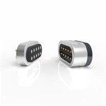
A 4 pin magnetic connector combines four electrical contacts with a magnetic mating structure. The magnets pull the two connector halves into position, while the contacts handle power, signal or a combination of both.
Xinteng supplies standard 4 pin magnetic connectors in different shapes, pin layouts, current ratings and mounting structures. For projects where an existing connector does not fit the enclosure or PCB, we can develop the connector from your 2D/3D drawing, PCB layout or sample.
The main difference between models is not simply the number of pins. Magnetic force, current requirement, connector shape, installation direction, available space and environmental protection all affect which 4-pin design will work in the finished device.
4 Pin Magnetic Connector Options
Our current 4-pin range includes straight, right-angle, compact and higher-current magnetic connector designs.
| Product Type | Key Specification | Magnetic Force | Suitable For |
|---|---|---|---|
| Magnetic 4 Pin Connector | 2.0 mm pitch, DC 60V, 1A, 10,000+ mating cycles | 600g ±20% | Compact power and signal interfaces |
| Right Angle 4 Pin Magnetic Connector | 2.2 mm pitch, DC 12V, up to 3A, 10,000 cycles | 800g ±20% | Devices with limited internal height or side-entry PCB layouts |
| Magnetic Power Connector | DC 12V, up to 5A, IP68 design, 10,000 cycles | 400g ±20% | Higher-current charging and protected power interfaces |
| Magnetic Pogo Pin Connector | 2.54 mm pitch, DC 12V, up to 2A | 700g | Charging and signal connections requiring a larger pin pitch |
The figures above belong to individual existing models. They should not be treated as one universal specification for every 4 pin magnetic connector. Final dimensions, electrical ratings and test requirements need to be confirmed against the selected product drawing.
How to Choose a 4 Pin Magnetic Connector


A useful starting point is the device itself rather than the connector catalogue.
Start with the Pin Assignment
Four contacts can be arranged for charging only or divided between power and signal.
A typical device may use two contacts for positive and ground, leaving the other contacts for a signal, detection line or another circuit function. A different project may allocate more than one contact to the power path.
The correct arrangement depends on the circuit and required current. If several contacts share the current load, the finished connector still needs to be checked for contact resistance and temperature rise under the actual working condition.
Check the Required Magnetic Holding Force
Magnetic force affects how the connector feels and behaves during use.
A stronger magnet is useful when the mating interface needs additional retention, but maximum attraction is not automatically better. A compact wearable or handheld product may need easy breakaway, while a fixed charging dock may require stronger retention.
Current products in this category use different magnetic forces rather than one standard value. The mechanical structure, connector weight, cable direction and expected pull force should therefore be considered together.
Match the Connector Shape to the Available Space
The enclosure often determines the connector structure before the electrical specification does.
Straight structures work where the connector and PCB can be positioned on the same axis. Right-angle pogo pin structures suit layouts where the mating direction is perpendicular to the PCB or where the product height is restricted. The existing right-angle 4-pin model, for example, uses bent contacts for a side-entry arrangement.
Round, racetrack and other housing shapes can also be used to match the industrial design of the device.
For a new enclosure, it is better to confirm the connector position during the mechanical design stage rather than trying to fit a finished connector into the remaining space.
Current and Charging Requirements
The current rating of a magnetic connector depends on the complete contact system, not the magnet.
Among the current 4-pin products on this page, published designs range from lower-current signal and charging interfaces to a 5A magnetic power connector. The 5A model uses a dedicated high-current structure and is rated at DC 12V.
For a new high-current project, we normally need to review the contact structure together with PCB pads, working stroke, contact resistance and temperature rise.
This is especially important when a small housing is expected to carry a relatively high current. Increasing the electrical rating without considering the mechanical space around the contacts can create unnecessary thermal problems.
Waterproof 4 Pin Magnetic Connector
Water resistance is available on selected structures; it is not a default feature of every magnetic connector.
For example, the current RM 200-4 pin magnetic power connector uses an in-mold structure and is specified as IP68.
For a custom waterproof connector, the pogo pins are only one part of the sealing design. The plastic housing, mating surface, installation method and the way the connector is integrated into the enclosure also affect the final protection level.
If waterproofing is required, provide the target IP rating and the product installation drawing at the beginning of the project.
Preventing Incorrect Mating
Magnetic attraction helps bring the male and female sides together, but the mechanical interface still needs to control orientation.
For products where reverse mating could cause a circuit problem, the housing can use an asymmetric shape, positioning feature or other mechanical restriction so the connector approaches in the intended direction.
This part should be considered together with magnet polarity and pin assignment.
A custom housing is often more useful than simply increasing the magnet strength when the main concern is alignment.
Standard Connector or Custom Design
A standard magnetic connector makes sense when its overall dimensions, current rating, magnetic force and mounting direction already match the device.
It also gives the engineering team a known connector to work with during the prototype stage.
A custom connector becomes necessary when the PCB position, enclosure opening, pin spacing or mating structure differs from the standard range.
Xinteng can work from customer drawings or samples to adjust the connector housing, contact arrangement, pin spacing, working stroke, magnetic structure and mounting method. The same project can also include non-standard pogo pins and precision-machined metal components when the electrical connector has to fit a customer-designed mechanical assembly.
The purpose of customization is not to redesign every connector from the beginning. We first check whether an existing part can be used or modified. A new structure is developed when the standard range cannot meet the mechanical or electrical requirement.
Applications
Typical applications include consumer electronics, charging docks, wearable products, portable medical equipment, beauty devices, smart appliances, handheld terminals and other compact electronic equipment.
New Energy Vehicles
More and more people’s requirements for automobile safety, eco-friendliness, comfort, intelligence, and other improvement. Automobiles also use more varieties and number of connectors and 4 pin magnetic connectors step by step. At present, the connector quantity is up to 1000 pieces in a new energy vehicle. And, of the total cost of a single new energy vehicle charging post, the cost percentage of all kinds of connectors is up 17.5%, including 4 pin magnetic connectors.
Aerospace
As precision components of aeronautical devices in space vehicles and satellite electronics. 4 pin magnetic connectors have different shapes, sizes, and material requirements to meet the uniqueness of different work tasks. For example, because of the extremely limited space available on a spacecraft, the 4 pin magnetic connector must be compact and small. and, pay attention to its weight. Of course, the most important thing is its reliability, it must have the ability to withstand severe environments, for example, external shock, extreme high and low temperatures, and vibration.
Ocean Engineering
If the underwater cables are arms and legs in all kinds of underwater equipment. Then, the underwater 4 pin magnetic connector like the joints, ensures that the normal work of underwater equipment is one of the important parts of the mechanical connection between the equipment. As well as the realization of the transmission of optical, electrical signals, and electrical energy. Suitable for a variety of ROVs, submarine cameras, and underwater sensors. Towed arrays, seabed observation networks, sea pastures, and other underwater applications. Are widely used in the field of ships, offshore oil, ocean exploration, and other marine engineering.
5G Communications and Data
4 Pin magnetic connector is one of the indispensable and important accessories in communication equipment and instruments. it has accounted for a relatively large amount of value in the communication equipment. With the deployment of 5G and the mass rollout of self-driving cars. 4 pin magnetic connector opportunities in telecom and datacom are expected to grow rapidly.
Military
4 Pin magnetic connector is also an essential component for new high-performance weapons. And equipment such as reconnaissance aircraft, missiles, smart bombs, etc. It is mainly used in aviation, aerospace, weapons, ships, electronics, and other high-tech fields. It requires tight manufacturing tolerances, rugged construction, high reliability, high cost, and resistance to harsh environments.
What Should Be Verified Before Mass Production?
The parameters shown on a product drawing need to be checked against the real assembly.
Depending on the project, verification may include current carrying performance, contact resistance, temperature rise, magnetic holding force, mating life, salt spray resistance, operating temperature and waterproofing.
For example, the current right-angle model is specified for 10,000 mating cycles, 24-hour salt spray testing and a maximum contact resistance of 50 mΩ. The higher-current RM 200-4 pin model is also specified for 10,000 mating cycles and has an IP68 structure.
Test requirements should be attached to the actual model or customer project. A result from one 4-pin connector should not automatically be applied to every product in the category.
Information Needed for a 4 Pin Magnetic Connector Quotation
For an existing product, send the product model or drawing together with the required quantity.
For a new connector, the most useful information is:
- 2D or 3D drawing, PCB layout or available installation space
- Required current and voltage
- Pin assignment and required pin spacing
- Connector dimensions and mating direction
- Preferred magnetic holding force
- SMT, DIP, right-angle or other mounting requirement
- Working environment and required operating temperature
- Target mating life
- Waterproof or corrosion-resistance requirement
- Estimated sample and production quantity
If the mechanical design is not finished, the available connector area and PCB position are enough for an initial evaluation. We can first check the standard product range before deciding whether a non-standard magnetic connector is necessary.
Custom 4 Pin Magnetic Connector From Drawing
Some projects reach us with a complete connector drawing. Others only have a PCB, enclosure model and electrical requirements.
Both can be evaluated.
For drawing-based development, the connector can be adjusted around the available opening, PCB location and mating direction. The housing, magnetic structure and contact layout are then matched to the device rather than forcing the product design around a catalogue connector.
If the assembly also requires special metal parts, Xinteng can combine connector development with precision machining so the mechanical interface and electrical contacts can be checked as one assembly.
Samples should be tested in the actual device before the design is released for mass production.
FAQ