


Draft Angle Requirements for Magnetic Cable Injection Molding: Technical Rationale and Failure Consequences
In the production of magnetic connector assemblies and cable overmolding, draft angle specification represents a critical design parameter that directly impacts manufacturability, cosmetic quality, and long-term reliability. Unlike standard plastic components, magnetic cable products involve insert molding-encapsulating permanent magnets, pogo pin contacts, and conductors within the polymer matrix. This hybrid construction amplifies the necessity of proper draft angles due to altered shrinkage patterns and mechanical interference risks during ejection.
Fundamental Principles of Draft Angle Design
Draft angle refers to the intentional taper applied to mold cavity walls, typically ranging from 0.5° to 3° depending on material properties. This geometric allowance compensates for plastic shrinkage during cooling, which causes the part to contract tightly around mold cores. Without adequate taper, the polymer forms a mechanical lock against vertical walls, generating extreme friction during ejection.
For magnetic cable applications, material selection dictates specific draft requirements. Soft elastomers such as TPE and TPU used for cable strain relief require 1°–3° due to high friction coefficients and elastic deformation characteristics. Engineering thermoplastics like PA66 typically need 0.5°–1.5°, while high-temperature materials essential for outdoor magnetic connectors-LCP (Liquid Crystal Polymer) and PPS (Polyphenylene Sulfide)-demand precise control at 0.5°–1°. These semi-crystalline materials exhibit high stiffness and limited ductility, making them particularly vulnerable to damage from forced ejection.
Consequences of Insufficient Draft
Surface Degradation and Contamination The most immediate manifestation involves surface defects. Hard engineering plastics like LCP and PPS develop stress whitening, scratches, and powdering along vertical walls. Soft TPE overmolding exhibits tearing and material transfer, where elastomer fragments adhere to the mold surface. In magnetic connector applications, these loose particles migrate to critical interfaces-contaminating pogo pin contact surfaces or interfering with magnetic mating faces-causing electrical intermittency or reduced magnetic retention force.
Mold Adhesion and Production Instability Insufficient draft causes parts to remain lodged in the cavity or core, preventing automatic ejection. Insert-molded components face elevated risk because embedded magnets alter local thermal contraction and create mechanical undercuts. Production lines experience frequent stoppages for manual part removal, drastically reducing cycle efficiency and increasing labor costs. In severe cases, parts split between mold halves, destroying both the component and potentially damaging delicate mold surfaces.
Structural Microcracking and Long-Term Reliability Failure Forced ejection generates concentrated stress at ejector pin locations. Brittle materials like LCP and PPS develop microcracks invisible to naked eye inspection. These subsurface fractures propagate during outdoor thermal cycling (-40°C to +125°C), creating pathways for moisture and salt spray ingress. For applications targeting five-year service life, such microcracking proves catastrophic-corrosion initiates internally, leading to spring force degradation in pogo pins or magnetic flux deterioration.
Dimensional Variability and Assembly Misalignment* Plastic deformation during forced ejection introduces batch-to-batch dimensional scatter. Critical features including magnet positioning pockets and pogo pin bores lose positional accuracy, resulting in magnetic misalignment, pin binding, or incomplete mating. The resulting assembly rejects often escape detection during initial inspection, manifesting as field failures under vibration or thermal stress.
Tooling Degradation* Repeated friction against undrafted walls accelerates mold wear, creating scoring and burrs on cavity surfaces. These tool defects subsequently imprint onto molded parts, establishing a cycle of declining quality that requires frequent polishing and maintenance interventions.
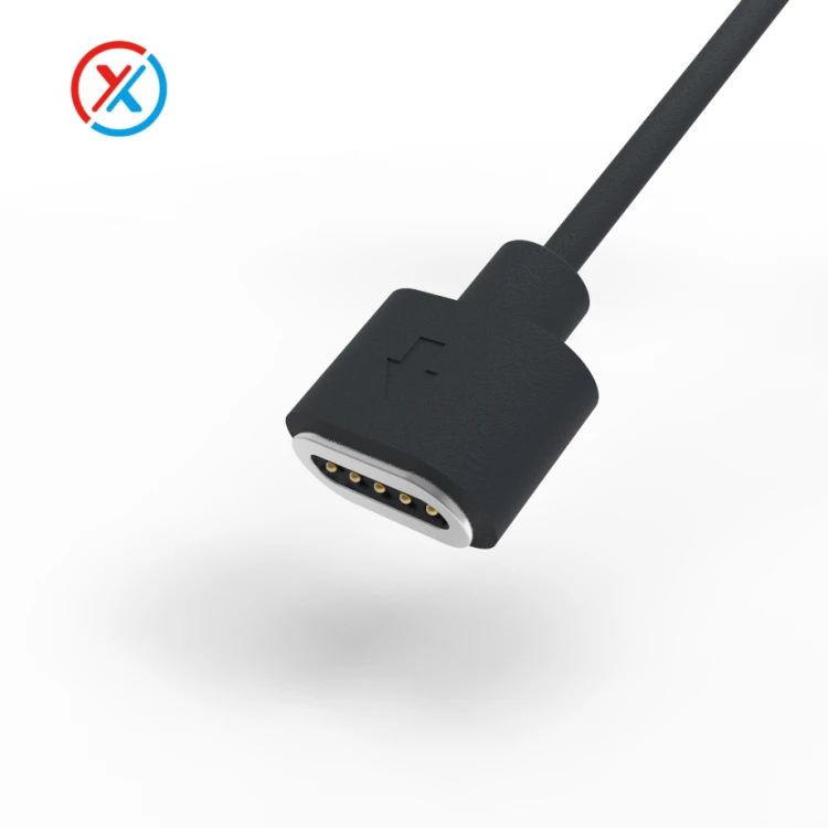
Design Compromises for Magnetic Interfaces
Engineers often specify zero-draft vertical walls on magnetic mating faces to ensure flatness and precise alignment. This requirement conflicts with manufacturability when applied to large surface areas. The solution involves restricting zero-draft geometry to small, localized regions combined with mirror-polished finishes and optimized ejector pin placement. Large peripheral surfaces must retain adequate draft angles to ensure reliable release. Attempting zero-draft across extensive areas in LCP or PPS yields poor yields and higher costs, making such specifications impractical for volume production.
FAQ
Q1: Can I specify zero draft on the magnetic mating face to improve alignment precision?
Localized zero-draft is feasible on small, flat regions (typically under 5mm diameter) with mirror-polished tool steel and advanced ejection systems. However, extending this to large surfaces guarantees sticking and damage. For your magnetic connector housing, we recommend 0.5° draft on peripheral walls while maintaining precision datum faces through post-machining or insert molding of metal reference surfaces. When submitting your housing design for manufacturing review, specify which faces require optical flatness versus which can accommodate draft, allowing us to optimize the mold architecture accordingly.
Q2: Why does my LCP housing show white marks after molding despite adequate draft?
White stress marks indicate either insufficient draft for the specific wall thickness, excessive ejection force due to undercuts, or premature ejection before adequate cooling. LCP requires complete crystallization before ejection; removing parts while core temperature remains above 80°C causes surface tearing. Verify that draft angles increase with wall thickness (minimum 1° per 2mm thickness for LCP) and ensure uniform cooling time.
Q3: How do insert-molded magnets affect draft angle requirements?
Embedded magnets create local thermal masses that alter shrinkage rates and can act as mechanical anchors against ejection. Increase draft by 0.5°–1° in regions surrounding metal inserts. Additionally, ensure magnet retention features incorporate draft to prevent the "anchor effect" where the polymer shrinks tightly around magnet edges.
Q4: What draft angle should I specify for TPE overmolding on cables?
Specify 2°–3° draft for soft elastomers, particularly where the overmold transitions to cable jacket. The high friction coefficient of TPE/TPU (typically 0.6–0.8 versus 0.3–0.4 for hard plastics) necessitates steeper angles to prevent tearing during ejection. For long overmold sections, consider adding longitudinal ribs with draft rather than relying on wall taper alone to reduce surface contact area.


