


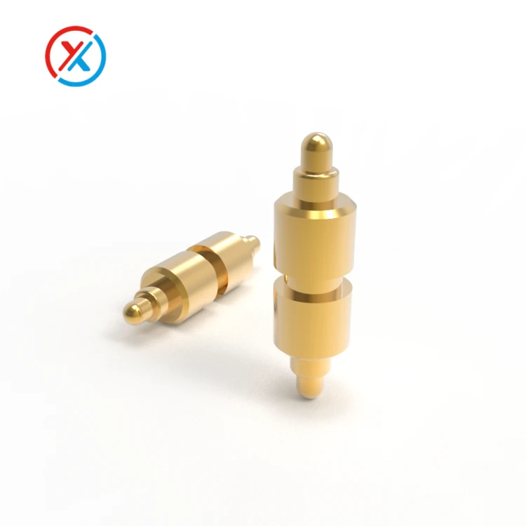
Short answer: yes - within strict boundaries. A double-ended pogo pin, with a plunger at both ends and a spring in the middle, bridges two PCBs by pressing its contact tips against pads on each board. Neither board is soldered. That single property makes it valuable, and that same property defines everything you must design around.
Where Double-Ended Pogos Earn Their Place
Separable board-to-board joints. The core use case: two PCBs that must mate and unmate repeatedly - a main board and a daughterboard in a magnetic connector assembly, for instance. Press together, pull apart, no damage, no wear on solder joints.
Tolerance absorption. The spring accommodates Z-axis stack-up variation and board warpage across a typical working stroke of 0.5–2 mm.
Low pin counts. Power plus a few slow signals - exactly the profile of most magnetic connectors, rarely exceeding 20 pins.
The Limits You Cannot Design Around
Pogo pins do not locate anything. The pin conducts electricity and nothing more - no alignment, no keying, no lateral force resistance. Without independent features constraining XY movement, the plunger tips skate across pads during mating and vibration, scraping plating and letting contact resistance drift. This is not a minor detail; it's the primary failure mechanism in the field.
Constant axial preload is mandatory. With no solder anchor, the joint depends entirely on external force - magnetic attraction, a latch, a screw - to keep both ends compressed. Insufficient preload under vibration produces momentary opens. In a magnetic connector design this works in your favor: the magnet's attraction is the preload.
Current capacity is modest, with doubled risk. Each pin typically carries 1–3 A depending on plunger diameter, and total path resistance stacks two contact interfaces in series - upper contact, spring, lower contact. Two contact surfaces means double the exposure to corrosion and contamination, and in salt-fog environments both demand precious-metal plating.
Not for high pin counts or high speed. Inter-pin crosstalk and added inductance make these unsuitable for high-frequency signaling. Power and low-speed signals only.
Fretting corrosion is the long-term enemy. Microscopic reciprocating sliding at the contact interface wears through the gold, oxides and sulfides accumulate, and resistance climbs slowly until the connection misbehaves - often years after installation. Outdoor thermal cycling plus vibration plus salt fog is the harshest combination this interface can face. Mitigation: PdNi under Au plating, controlled compression, minimal lateral displacement, and structural limits on board-to-board play.
Versus Traditional Board-to-Board Connectors
Soldered BTB pairs bring their own alignment features and resist lateral loads, but they sacrifice separability. Double-ended pogos reverse that trade: infinitely remateable, but dependent on the surrounding structure for everything the BTB connector gave you for free.
Structural Design Essentials for a Magnetic Assembly
Build a module. Multiple double-ended pins fixed in an insulator housing form the pogo module - a unit worth designing and procuring as one precision part rather than an assortment of loose pins.
Add locating posts. Molded alignment pins engaging holes in both PCBs eliminate XY slip, which is the single most effective fretting countermeasure available.
Size the magnet for total spring force. Magnetic attraction must exceed the summed spring forces of every pin, with each pin operating in roughly the 30–70% of rated travel - clear of both zero-contact slack and solid-bottom over-compression.
Specify the pad plating. Pads should be larger than the plunger tip, finished with Ni + PdNi + Au - consistent with outdoor contact requirements - rather than solder-tin finishes, which wear and oxidize poorly under sliding contact.
Control planarity. Board warpage distributes compression unevenly across pins; the flattest pin carries the joint until it doesn't.
Making It Manufacturable
Precisely because the module and its locating geometry carry the entire interface, these small assemblies reward tight mechanical control. In our workshop we regularly produce the insulator housings, locating-post fixtures, and retaining plates for pogo modules directly from customer drawings - single pieces for prototyping, small batches for pilot lines - holding the position tolerances that keep ten or twenty pins compressing evenly. A module that locates within ±0.03 mm behaves nothing like one built to ±0.1 mm, and the contact resistance traces will tell you which one you have.
Frequently Asked Questions
Q1: Can double-ended pogo pins fully replace board-to-board connectors?
No. They suit separable, low-pin-count, power and slow-signal joints where an external structure supplies alignment and preload. High pin counts, high-speed signals, or assemblies without a reliable clamping force belong on conventional BTB connectors.
Q2: Why does contact resistance drift after a few years outdoors?
Fretting corrosion. Micro-motion at the contact interfaces wears the gold layer, and oxides or sulfides accumulate beneath it, raising resistance gradually. Prevention means PdNi/Au plating, eliminating lateral slip through positive location, limiting board play, and keeping compression in the designed window.
Q3: What plating should the PCB pads have?
Ni + PdNi + Au. Tin finishes are inappropriate for sliding contacts - they smear, oxidize, and raise resistance. The pad should also be sized generously relative to the plunger tip to tolerate alignment tolerance.
Q4: How much magnetic preload is enough?
The magnet must overcome the sum of all pin spring forces at working compression, with every pin operating between 30% and 70% of its rated travel. Under-spec the magnet and vibration produces momentary opens; over-spec and mating force becomes unpleasant and mechanical wear accelerates. Calculate from the actual spring force curves, not catalog averages.


