


The exact process depends on the connector structure, number of Pogo Pins, magnetic arrangement, cable or PCB termination, waterproof requirements, current rating, and installation method. For a standard magnetic connector, many operations can be standardized. A non-standard connector usually requires additional tooling, fixture development, dimensional validation, and sample testing before mass production.
1. Incoming inspection of raw materials and components
Production starts with incoming quality inspection. The purpose is to confirm that the materials and purchased components meet the approved drawings and specifications before they enter machining or assembly.
Metal contact parts are checked for material, dimensions, surface condition, burrs, and deformation. Pogo Pin components require additional checks on free height, movement, spring force, and contact condition.
Magnets are inspected for dimensions, polarity, magnetic strength, coating condition, and orientation requirements. Incorrect magnetic polarity can affect the mating direction and holding behavior of the finished connector.
Plastic housings and insulating parts are checked for dimensions, molding defects, deformation, and material requirements. Cable assemblies may also require checks on conductor size, insulation condition, length, and termination quality.
Surface treatment is inspected according to the approved specification. For plated contacts, the relevant coating thickness, coverage, adhesion, and appearance should be verified at the locations that actually participate in electrical contact.
Good incoming inspection prevents a defective component from moving into a more expensive assembly process.
2. Precision processing of connector components
Once the incoming materials are approved, individual components are processed according to their drawings.
Metal contact parts may be manufactured by precision turning, stamping, grinding, or other forming processes. Pogo Pin barrels, plungers, contact terminals, mounting sleeves, and other small metal components require controlled dimensions because their fit and electrical performance depend on relatively small geometric differences.
Springs are formed according to the required force and working range. Their finished characteristics need to be checked rather than judged only by appearance.
Magnets are prepared according to the required size, coating, polarity, and mounting position. Plastic housings can be produced by injection molding when the design requires an insulating carrier or a shaped connector body.
Surface treatment is normally performed after the relevant metal components reach their required geometry. The selected finish depends on electrical load, mating cycles, environmental exposure, and cost requirements.
Dimensional consistency becomes especially important for multi-pin connectors. Contact pitch, pin height, housing position, and magnet location all have to remain within the defined tolerance range so that the two mating halves can locate correctly during assembly.
For equipment with a non-standard connector installation, the surrounding mechanical parts may also need to be manufactured specifically for the application. We support drawing-based precision machining of locating seats, mounting plates, brackets, sleeves, shafts, and other dedicated components. For packaging machinery, these parts can be produced as one-off or small-batch non-standard components according to customer drawings, allowing the connector position and machine-side mounting structure to match the actual equipment.
3. Component assembly and positioning
After individual components have passed inspection, they are assembled into the magnetic connector.
For a Pogo Pin magnetic connector, the assembly may include Pogo Pins, springs, barrels, magnets, insulating components, housings, PCBs, and cables. The exact combination depends on the product structure.
Pogo Pins must be installed at the specified positions and heights. The assembly fixture needs to control the contact pitch and prevent the pins from tilting during installation. Incorrect positioning can result in uneven contact pressure when the connector is mated.
Magnet orientation also requires process control. Magnets with the wrong polarity or incorrect position can cause poor attraction, incorrect mating, or inconsistent holding force.
For cable-type magnetic connectors, the cable may be soldered, crimped, or otherwise terminated before the connector body is completed. The connection between the cable and contact assembly needs mechanical support because repeated cable movement can otherwise transfer stress directly to the electrical joints.
Adhesives may be used to secure magnets or other internal components. When adhesive curing is part of the process, curing temperature and time need to be controlled so that the adhesive reaches the required condition without contaminating the contact area.
Assembly fixtures are often designed specifically for the connector structure. For customized products, the fixture can be developed around the customer's PCB, housing, mounting position, and mating interface rather than forcing the application to use a standard connector geometry.
4. Molding and sealing
The next stage depends heavily on whether the connector requires environmental protection.
For a basic magnetic connector, the housing may simply be assembled around the completed contact and magnet structure. For waterproof versions, additional sealing measures are required.
Common approaches include injection molding, overmolding, sealing rings, adhesive sealing, or a combination of these methods. Cable-type products may use overmolding to cover the connector and cable termination with a continuous protective structure.
During molding, the position of the internal contacts and magnets must remain stable. Excessive molding pressure or incorrect component positioning can change the final contact height or damage internal parts.
Sealing materials also need to stay away from the moving portions of the Pogo Pins. If sealing material enters the barrel opening or contact area, it may increase friction, restrict spring movement, or create an unstable electrical connection.
For waterproof magnetic connectors, the finished assembly must be tested according to its specified protection requirement. An IP rating should be associated with the tested connector configuration and installation condition rather than assumed from the use of a sealing material alone.
The same principle applies to mechanical protection. A molded housing should provide the required support and clearance while preventing unnecessary loads from being transferred to the Pogo Pins.
5. Final inspection, functional testing, and packaging
The final stage checks whether the completed connector meets the approved product requirements.
Dimensional inspection may include overall size, mounting dimensions, contact position, pin projection, and connector alignment. Electrical inspection can include continuity and contact resistance measurements, with the inspection frequency determined by the product specification.
Mechanical testing may check Pogo Pin movement, spring return, mating behavior, magnetic retention, and other characteristics relevant to the connector design.
For products intended for repeated connection, cycle testing can be performed to evaluate changes in contact resistance, spring movement, magnetic retention, and surface wear. Environmental tests such as temperature cycling, humidity, corrosion, or waterproof testing may also be included when required by the application.
Visual inspection remains useful at this stage. Operators can identify damaged housings, scratches, exposed metal, incorrect magnet orientation, molding defects, cable damage, or other abnormalities that electrical testing alone may not detect.
After final acceptance, connectors are packaged in a way that protects the contact surfaces and prevents deformation during transportation. Packaging can also include model identification, polarity information, lot numbers, and traceability records where required.
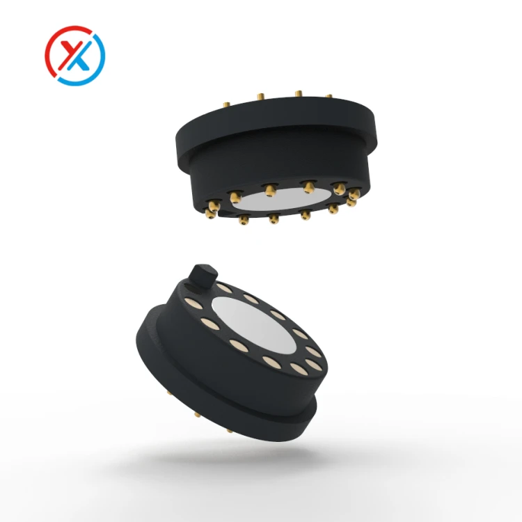
Why process control matters in magnetic connector production
The five stages are connected. A dimensional error introduced during component machining can become an alignment problem during assembly. A plating defect may later appear as increased contact resistance. Incorrect magnet positioning can affect mating behavior, while poor molding control can alter the position of the internal contacts.
For this reason, magnetic connector manufacturing is not simply a matter of assembling magnets and Pogo Pins. The machining, surface treatment, assembly, molding, and inspection processes need to work from the same approved dimensional and performance requirements.
For customized projects, this becomes even more important. A connector designed for a particular piece of equipment may require non-standard contact spacing, housing dimensions, mounting structures, cable exits, or locating components. These parts can be developed from customer 2D drawings or 3D models and validated through prototype or small-batch production before volume manufacturing.
In packaging machinery and automated equipment, the connector is often installed together with dedicated mechanical components. Precision-machined mounting blocks, locating plates, guide sleeves, brackets, and other machine parts can be manufactured according to the customer's drawings so that the electrical interface and mechanical structure work together as intended.
FAQ
What are the main steps in magnetic connector manufacturing?
A typical process includes incoming inspection, precision component processing, component assembly, molding or sealing, and final inspection and packaging. Additional operations such as plating, cable termination, magnetization, or reliability testing are added according to the connector design.
Does every magnetic connector require injection molding?
No. The housing structure determines the process. Some connectors use assembled plastic or metal housings, while waterproof or integrated cable designs may require insert molding or overmolding.
Why is magnet positioning important during production?
Magnet position and polarity affect how the two connector halves approach each other and how much holding force the finished assembly provides. Incorrect positioning can cause poor alignment or inconsistent mating behavior even when the electrical contacts themselves are correctly assembled.
Can non-standard magnetic connector components be manufactured from customer drawings?
Yes. When a standard component does not fit the required installation, connector housings, mounting structures, locating parts, sleeves, brackets, and other precision components can be produced from customer drawings. For packaging machinery, single-piece and small-batch machining can be used when dedicated machine-side components are required.


