


In a mobile device, the battery connection links the battery assembly to the main circuitry. Space around that interface may be shared with structural supports, shields, flexible circuits, and other components.
A lower connector profile can help the mechanical layout, but the usable height must include the complete mating arrangement. The connector halves, FPC thickness, reinforcement, solder joints, and surrounding clearances all need consideration.
"Board-to-FPC" describes the parts being connected. It does not identify the contact mechanism or establish that the connector uses pogo pins. The actual construction must be defined in the drawings and product specification.
For a proposed 0.6 mm design, the height measurement needs a reference. It may describe the mated connector height, a component's individual height, or a distance between specified mounting surfaces. These dimensions are not interchangeable.
The tolerance range matters as much as the nominal value. The assembly must engage correctly across variations in the connector, PCB, FPC, and supporting structure. A nominal fit is insufficient if production variation leaves some contacts inadequately engaged.
The 20 A requirement needs similar clarification:
| Design parameter | Proposed reference | What must be confirmed |
|---|---|---|
| Connector height | 0.6 mm target | Measurement reference, mated condition, and tolerance |
| Current capacity | 20 A target | Continuous or peak duty, duration, and applicable contact arrangement |
| Operating voltage | Application-dependent | Normal voltage and relevant electrical conditions |
| Contact resistance | To be specified | Measurement points, initial limit, and allowable change after testing |
| Retention force | To be specified | Test direction, speed, engagement condition, and acceptable range |
| Thermal performance | To be specified | Ambient temperature, installation, load, and temperature limits |
| Mating life | Application-dependent | Expected assembly and service cycles, with acceptance criteria |
Battery capacity alone does not determine connector current. The required current follows the device's operating load, charging architecture, and transient demands. The battery-side current may also differ from the current at an external charging port.
A continuous rating must be supported under defined thermal conditions. A short-duration peak requires its own duration, repetition rate, and starting conditions. These should not be combined into a single unexplained "maximum current" value.
The complete supply and return paths must each carry the circuit current. Their ratings are not added together. Where several contacts share one path, the design also needs to account for unequal current distribution caused by resistance and engagement differences.
Resistance has a significant thermal effect at higher current. For illustration, each 1 mΩ of series resistance dissipates 0.4 W at 20 A. The resulting temperature rise depends on how heat leaves the contacts, terminations, PCB, and FPC.
This makes the surrounding conductors part of the connector evaluation. FPC conductor thickness, width, length, transitions, and termination geometry can affect both voltage drop and heating. PCB copper and the enclosure's thermal conditions also matter.
Testing a connector with conductors that dissipate heat more effectively than the intended installation can give an unrepresentative result. Validation should therefore use the proposed FPC, PCB, mating parts, and relevant enclosure conditions.
Mechanical retention requires a separate specification. Withdrawal force measures resistance to separation, while contact normal force acts at the electrical interface. The two are related through the design but are not the same parameter.
High withdrawal force does not by itself prove low contact resistance or resistance to intermittent connection. Excessive removal force can also complicate service or transfer unwanted loads into the FPC and its mounting.
Guidance, polarization, mechanical support, and strain relief should keep assembly and handling loads away from vulnerable contact and termination areas. If the battery connection is intended to be serviced, the design should provide a controlled engagement and release method.
Contact materials and finishes need to suit the electrical load and mechanical requirements. Conductivity, strength, wear behavior, corrosion performance, and manufacturing consistency should be evaluated together.
Gold or another contact finish may help maintain surface stability, but plating alone does not establish a 20 A rating. Bulk conductor resistance, contact geometry, normal force, and heat dissipation remain important.
Qualification should address the installed interface, including electrical resistance, voltage drop, temperature under load, engagement and withdrawal forces, and performance after relevant mechanical and environmental exposure.
An internal battery connector may experience relatively few service cycles while remaining engaged for long periods. Force retention, temperature exposure, and continuity during specified vibration or shock may therefore be important alongside repeated mating.
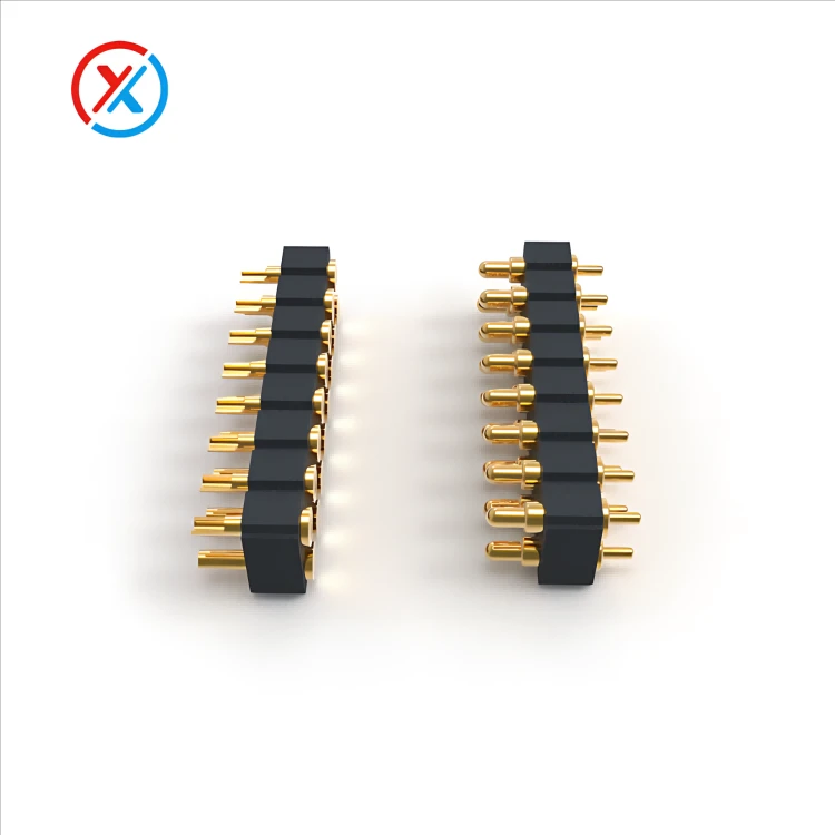
XINTENG supports drawing-based customization of pogo pin contacts and connector assemblies. Where a spring-loaded interface is being considered for a battery connection, the development review can assess installation space, working compression, conductive paths, retention, and termination requirements.
Samples or small-batch assemblies can then be evaluated against an agreed specification. Compatibility with a 0.6 mm height target or a 20 A current target must be established for the proposed design rather than inferred from another connector.
Approved drawings, material and finish specifications, test results, and inspection criteria should remain linked to the evaluated configuration. Production approval should identify the exact assembly and operating conditions covered.
1. Does a 0.6 mm connector height establish 20 A capability?
No. Height and current capacity are separate requirements. Both must be achieved and verified in the same proposed assembly.
2. Does 20 A mean each contact can carry 20 A?
Not necessarily. It may refer to a complete power path, several parallel contacts, or a peak condition. The specification must state which interpretation applies.
3. Does stronger retention improve electrical reliability?
Suitable retention helps maintain engagement, but electrical reliability also depends on contact force, geometry, surface condition, and resistance. Withdrawal force alone is insufficient evidence.
4. What information is needed to evaluate a custom battery connector?
Provide PCB and FPC drawings, the height definition, voltage, continuous and peak current requirements, available thermal conditions, mounting details, service requirements, and acceptance criteria.


