


What Counts as a Pogo Pin Connector on a Mobile Phone?
When a phone drops into a charging cradle, the cradle walls guide it into position. In a typical arrangement, spring-loaded pins project from the dock and press against flat pads on the handset. Each plunger retracts into its barrel as the phone settles against the cradle's supporting surface. The spring maintains contact pressure, while the cradle sets the final position and limits compression.
The pads may also belong to a protective case. A case can connect to the phone through its USB-C port and route power to exposed pads on the case exterior. When changing phone models, check the port position, case width, camera opening, and distance from the docking surface to the pads. A new handset can fit the same charging system only if its case preserves the mechanical and electrical interface the dock expects.
Magnetic attachment describes how the parts come together. In a magnetic pogo pin cable, charging current crosses the interface through metal contacts. In a magnetically aligned wireless charger, the magnets position the phone and power crosses the gap through coils. A case that fits a wireless charger needs a separate conductive interface to work with a pogo pin dock.
Which Pogo Pin Connector Types Are Used With Mobile Phones?
| Product format | Where it fits | What to check first |
|---|---|---|
| Individual pogo pins | A dock PCB needs contacts at custom positions, perhaps on opposite sides of an existing phone port. | Check each pin's position, installed height, working travel, and landing point on its pad. |
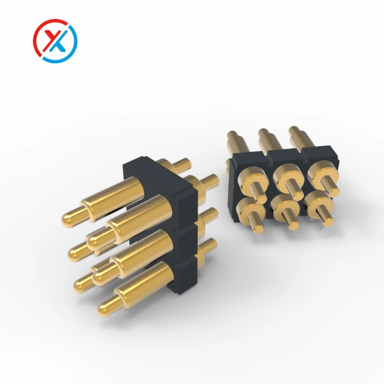
| Housed pogo pin array | Several contacts mate with a defined pad pattern on a handset or case. An insulating housing holds the pins at a specified pitch. | Check pin count, pitch, and the position of the whole row relative to the dock guides. Check tip height variation and the combined spring force. |
| Magnetic pogo pin assembly | A charging cable, desktop dock, or vehicle mount needs quick attachment and removal. | Check the permitted mating direction, magnet polarity, holding force, and compression of every pin when the two faces seat. |
These formats overlap. A magnetic cable head may contain a housed two-pin array. Surface mount, through-hole, and solder-cup termination describe how the connector attaches to a PCB or cable. A buyer therefore needs both details when requesting a sample, such as "two-position housed array with surface-mount terminals."
What Is the Difference Between Charging-Only and Multi-Function Connectors?
Charging-only interfaces need a defined supply and return path. Confirm polarity from drawings that identify the viewing direction, since the phone-side and dock-side mating views face each other. At the intended continuous current, measure the voltage drop through the cable and across both mating contacts. Record terminal temperature after it stabilizes. For fast charging, verify the protocol supported by the phone, dock electronics, and power source together.
Charging and data interfaces need a pin-by-pin definition. One documented example is the Fusion handset. Its Development Toolkit, version 3.0, shows six contacts in a row on the back of the phone itself.
| Pins | Drawing labels | Function on the Fusion handset |
|---|---|---|
| 1 and 5 | VBUS and GND | Power and return. The direction of power flow depends on the accessory's operating mode. |
| 2 and 3 | DP and DM | USB 2.0 data pair. |
| 4 | OTG | Supports USB host or accessory role selection. |
| 6 | ADC | Reads an analog value supplied by the accessory. Applications can use the value for identification or status. |
For this model, the toolkit specifies up to 15 W from a compatible accessory to the phone and up to 5 W from the phone to an accessory. It also provides sample software for reading the ADC pin. A complete accessory test should exercise each intended function: charge the handset under load, transfer data through the dock and cable, and check that the application recognizes the attached accessory. Another six-contact product requires its own pinout.
How Do You Match the Connector to the Phone, Case, and Dock?
Check sideways movement at the pads. Use the surfaces that actually locate the handset, such as the cradle sidewalls and lower stop. Include any movement allowed by the case, then overlay the pin tips on the pad drawing at both extremes. Check whether a raised camera surround or case lip touches first and tilts the phone.
A simple calculation shows how quickly the available margin disappears. Suppose a pad is 1.6 mm wide and the design requires a 0.6 mm tip to stay fully inside it. A centered tip has 0.5 mm of margin on either side. If the tolerances allow 0.4 mm of sideways movement from center, just 0.1 mm remains on the nearer side. These illustrative dimensions cover one direction. The same check is needed along the pad's other axis.
Check the largest and smallest assembly gaps. At the largest gap, the shortest installed pin must still develop the required contact force. At the smallest gap, the tallest pin must remain within its permitted working travel. For a magnetic interface, close the complete assembly with every pin installed. The combined spring force can hold one edge off its seat even when each pin works correctly in isolation.
Test the way the phone will be handled. For a pocket-carried handset, inspect the contact area after exposure to lint and perspiration and after the intended cleaning procedure. For a vehicle dock, monitor interruptions during vibration. For a frequently used desk cradle, include angled insertion and removal in the cycle test. Record resistance, loaded voltage drop, and contact marks on the same samples so an electrical change can be matched to a wear location.
Selection Example: A Charging Dock for a Rugged Handheld Phone
The March 2023 single-slot dock datasheet for the XCover Pro and XCover6 Pro documents a practical arrangement. The XCover6 Pro model uses a shaped cradle and pogo contacts to supply power to the handset at its lower docking interface. The dock receives power through an integrated USB-A cable. Its published outer dimensions are 4.5 inches wide, 3.75 inches deep, and 2.0 inches high. Designing a replacement contact assembly still requires the internal mounting space, pad coordinates, polarity, and permitted charging current.
Consider a teaching example for a replacement dock with two power pads and an assumed 1 A continuous load. The 1 A figure is a design input for this example. The first sample decision depends on the mating drawing:
| Candidate | When to sample it | What decides acceptance |
|---|---|---|
| Standard two-pin housed array | The pad spacing matches an available array, and its housing fits behind the cradle's lower stop. | Both tips land within their pads at maximum offset and provide adequate force at the largest gap. |
| Individual pins or a custom housing | The pads have irregular spacing, straddle an opening, or sit too far from the mounting reference for a standard array. | The revised layout reaches both pads within the available space and keeps the pins aligned during insertion and removal. |
For either sample, mark the tip locations at centered and worst-case positions. Apply the agreed load and measure the voltage drop from each dock terminal to its mating pad. Repeat after the specified docking cycles and inspect the wear marks. Those records give the buyer a basis for approving the production drawing.
For a custom phone dock, Dongguan Xinteng Electronics Co., Ltd. can review the phone or case drawing against standard pins and housed arrays. Pad coordinates, polarity, minimum and maximum installed gaps, continuous current, and the available mounting space are the most useful details to send with a sample request.
Technical References
Fusion Development Toolkit, version 3.0, March 2025. Hardware Interface, Power Specifications, and ADC Detection sections.
Charging for XCover Pro and XCover 6 Pro, single-slot charging dock datasheet, March 2023. Phone compatibility, charging interface, and dock dimensions.


