


Step 1. Review the Drawing and Define the Inspection Criteria
Start with the drawing of the mating part. The pad dimensions and positions determine where each tip can land. The smallest and largest distances between the assembled parts determine how far the plungers will compress. Check these dimensions from the same mounting reference, along with pin count, pitch, and the surface-mount or through-hole footprint.
The drawing should tell an inspector how to reproduce each measurement. For contact force, specify the working height or compression distance and the allowable force range. For contact resistance, identify the mating surface and the two voltage-sensing points. For a close sliding fit, state whether the dimension applies before or after plating.
For a custom connector, Dongguan Xinteng Electronics Co., Ltd. can review the mating drawing and identify which standard parts will fit. A change in pin spacing may require only a new housing. A smaller mating pad may call for a different tip, while a change in board mounting may require a different barrel base or solder tail. Making that distinction early keeps the sample build focused on the parts that affect fit.
Step 2. Manufacture the Plunger, Barrel, and Spring
| Part | How it is made | What to inspect |
|---|---|---|
| Plunger | In a turned design, a precision lathe forms the contact tip, the cylindrical guide surface, and the internal end that bears on the spring. | Check the tip profile against the pad drawing. Inspect the guide surface and shoulder for burrs or tool marks that could catch inside the barrel. |
| Barrel | Machining forms the bore, barrel mouth, and mounting end. The mounting end may have a through-hole solder tail or a flat surface-mount base. | Check the bore diameter and depth, the material left at the mouth for forming, and the tail or base dimensions against the PCB footprint. |
| Spring | Spring wire is wound to the specified coil geometry. The spring may be made in-house or purchased to a component drawing. | Verify the material, wire diameter, free length, and force at a specified compressed length. Record the manufacturing or supplier lot so it can be traced after assembly. |
A spring can meet its own force specification while the assembled pin still binds. Keeping the bare-spring measurement and the finished-pin measurement separate makes that fault easier to locate.
Step 3. Clean, Plate, and Inspect the Contact Surfaces
After machining, remove burrs, cutting oil, and loose chips. The barrel bore deserves a separate check. A chip trapped near the closed end can interfere with the spring and becomes difficult to see once the plunger is in place.
For production, the plating instruction also needs to identify the surfaces covered and where thickness will be measured. ISO 3497 describes X-ray methods for measuring metallic coatings. A reading from the barrel exterior establishes thickness at that location. If the internal sliding surface has its own requirement, agree on a suitable inspection method for that surface. Check the finished bore and plunger together as well, since plating changes the clearance between them.
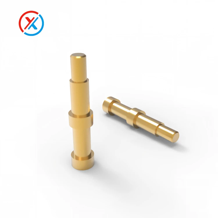
Step 4. Assemble the Spring-Loaded Pin and Retain the Plunger
In a rolled-lip design, the spring goes into the barrel first, followed by the plunger. A forming tool rolls the barrel mouth inward over the plunger shoulder. The lip must capture the shoulder while leaving the guide section free to slide through the opening.
Three checks follow. Press and release the plunger to check for smooth travel and full return. Measure its free height from the mounting reference. Then load the pin along its axis and record the force at the specified working height.
A slow-returning plunger gives the inspector a specific fault to investigate. Check for debris in the bore, measure the clearance after plating, inspect the formed lip for an uneven or undersized opening, and examine the assembly for tilt. Replacing the spring alone can leave the cause untouched.
Step 5. Install the Pins in the Connector Housing
Inspect the molded housing from the features that locate it in the device. Check the pin holes and locating features against those references, then seat and retain each barrel as the drawing specifies. On the finished connector, measure each tip position relative to the mounting reference. Adjacent pins can have the correct pitch even when the entire row sits too far to one side.
Two height checks serve different purposes. Tip height variation affects whether every pin reaches its pad when the device closes. Solder-terminal coplanarity describes how evenly the surface-mount ends sit against the PCB. A connector can meet one requirement and fail the other.
For a magnetic connector, verify magnet orientation and polarity against the actual mating half. Close the complete pair and confirm that the magnets keep both faces seated while all springs are compressed. A single-pin force test cannot establish that the assembled dock will close fully.
Step 6. Verify Electrical Performance and Durability
| Test | Conditions to record | Acceptance question |
|---|---|---|
| Contact resistance | Mating pad material and finish, working height, four-wire sensing points, and test method. IEC 60512-2-1 defines a millivolt-level method. | Does the resistance across the specified mated path stay within its limit? |
| Contact force and travel | Mounting reference, loading direction, compression distance, force at working height, and return after release. | Does each pin provide the required force throughout the intended assembly range? |
| Temperature rise under load | Current, number and location of energized pins, PCB or wire configuration, ambient temperature, and terminal measurement point. | Does the hottest terminal remain within the product limit once its temperature stabilizes? |
| Mating durability | Mating finish, stroke, cycle count, electrical load during mating, and failure criteria. | After cycling, are resistance, force, and pad wear still acceptable? |
The inspection plan assigns these checks to the appropriate stage. A line might check every pin for free movement, measure force on a defined sample from each lot, and reserve thermal and endurance testing for design qualification or an agreed production change. A supplier's qualification report and a shipment inspection record answer different questions. The first documents the tested design. The second identifies what was checked on the lot being shipped.
Step 7. Release, Package, and Trace the Production Batch
For loose parts, choose packaging that protects projecting tips and slender solder tails during transport. For tape-and-reel delivery, check pocket fit, feed direction, component orientation, and the pick-up position against the customer's placement process.
Contact force illustrates how a requirement reaches the shipping decision. The CPG-16-SMT-B datasheet specifies 25 to 55 gram-force (gf) at a working height of 2.50 mm, with 40 gf typical. An inspector using that requirement must set the fixture to 2.50 mm from the specified mounting reference. A reading of 24 gf at that height would fall below the limit, even if the lot average were close to 40 gf. The agreed sampling plan determines the next action for the lot.
The batch record should connect the drawing revision and plating lot to the assembly measurements, sample quantity, and release decision. The same lot identifier belongs on the reel or package. If a customer later reports intermittent charging, that identifier gives the investigation somewhere concrete to start: the finish applied to those parts, the force recorded at working height, and the position of the pins after housing assembly.
Technical References
ISO 3497:2000. Metallic Coatings - Measurement of Coating Thickness - X-ray Spectrometric Methods. International Organization for Standardization.
IEC 60512-2-1:2002. Connectors for Electronic Equipment - Tests and Measurements - Part 2-1: Electrical Continuity and Contact Resistance Tests - Test 2a: Contact Resistance - Millivolt Level Method. International Electrotechnical Commission.


