


A phone may use flexible-circuit connectors, board-to-board connectors, external I/O interfaces, coaxial connections, and spring contacts in different locations. Each serves a particular purpose, so selection should begin with the circuit and mechanical arrangement.
FPC and FFC terminology needs care. An FPC is a flexible printed circuit with patterned conductors and potentially more complex routing. An FFC is a flat flexible cable, typically containing parallel conductors within an insulating structure.
Some connectors accommodate either type when the mating dimensions and contact arrangement are compatible. Others are intended for a specific cable or flexible-circuit construction. The names alone do not establish interchangeability.
For a flexible connection, confirm the contact count, pitch, mating thickness, exposed conductor dimensions, insertion depth, and contact orientation. The stiffener and cable entry direction also affect fit and assembly.
A connector that appears correct in a drawing may still be difficult to use if the latch is inaccessible or the flex must bend sharply near the termination. The surrounding enclosure and assembly sequence should therefore be reviewed with the connector.
| Connector category | Typical design role | Details to confirm |
|---|---|---|
| FPC/FFC connector | Connects a compatible flexible circuit or flat cable to a PCB | Cable thickness, contact orientation, pitch, latch operation, and routing |
| Board-to-board connector | Connects two circuit boards through mating connector halves | Mated height, footprint, alignment, retention, and board support |
| External I/O connector | Connects charging cables or external accessories | Interface requirements, mechanical fit, electrical compatibility, and durability |
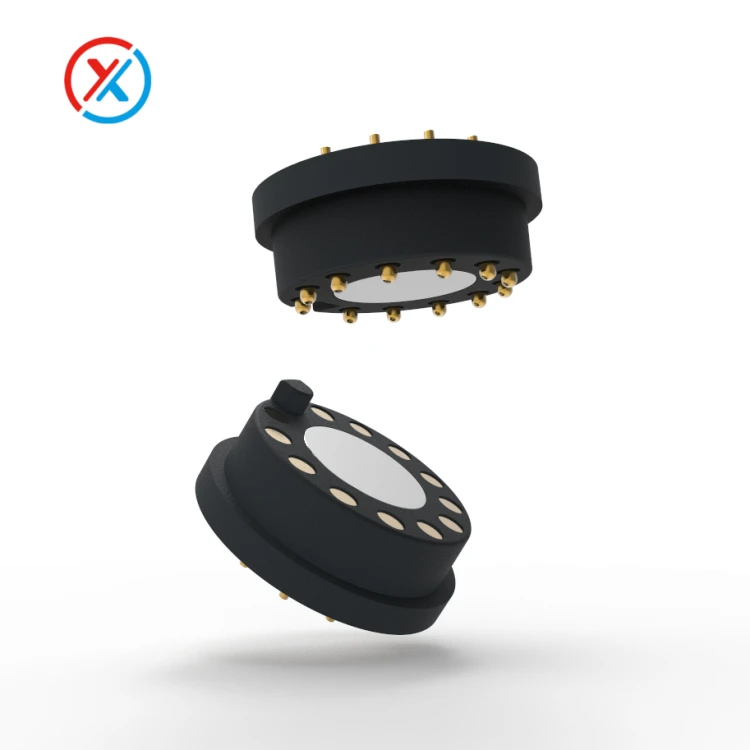
| Pogo pin interface | Provides pressure contact for selected internal, docking, or accessory connections | Working compression, mating pads, retention, and electrical performance |
Board-to-board connectors require a clear definition of the installed relationship between the boards. Mated height, component clearance, board thickness, and enclosure tolerances all contribute to the available space.
The mounting structure should keep the boards aligned and supported. A connector should not be expected to correct excessive positioning errors or carry loads beyond its specified capability.
Assembly access matters as well. The production team needs a controlled way to engage the mating halves without tilting, damaging contacts, or applying excessive force. Service access may introduce further requirements if the boards must be separated later.
Electrical performance should be established for the actual circuit. Power contacts need suitable current capacity and temperature performance. Signal contacts need characteristics appropriate to the interface and complete transmission path.
A current rating should be reviewed with its test conditions, including ambient temperature, conductor arrangement, and the number of simultaneously loaded contacts. Resistance and heat in the PCB connections or flexible circuit can limit the assembly even when the connector itself appears adequately rated.
For high-speed signals, pin arrangement, return paths, PCB transitions, and flexible-circuit routing all matter. Low DC resistance does not establish bandwidth or signal integrity. Relevant supplier data should describe the configuration to which it applies.
External I/O connectors introduce compatibility requirements that extend beyond the phone enclosure. The device must work correctly with the intended cables, chargers, and accessories.
Changing the pin count or assignments of a standardized interface can invalidate its expected compatibility. A familiar connector shape does not make a modified electrical arrangement interchangeable with the original interface.
Using an existing connector can reduce development work when it meets the requirements. Any changes to its mating geometry, contact arrangement, shielding, or electrical function need review against the intended interface.
A proprietary connector may be appropriate for a dedicated accessory or dock. In that case, both mating halves, pin assignments, electrical behavior, and supported accessories must be defined together.
Compact dimensions should be evaluated alongside manufacturability. Smaller pitch and lower height can make placement, alignment, inspection, and rework more demanding. The smallest available part may not produce the lowest assembly cost or the best production yield.
Contact materials, plating, and insulating materials should also suit the electrical load, assembly heat exposure, and environment. A finish suitable for a solder termination may serve a different purpose from the finish on a repeatedly mated contact.
Durability requirements should reflect actual use. An internal connector assembled during manufacture faces a different mating pattern from an external charging interface. Drop, vibration, temperature, contamination, and service handling may be more relevant than a high cycle count alone.
Supplier selection requires a similar focus on the actual project. A nearby factory may simplify communication, transport, or visits, but distance alone does not determine total cost.
Nominal production capacity also provides limited information without understanding available capacity, tooling, materials, process constraints, and order scheduling. A larger factory is not automatically the most economical supplier for a small or specialized order.
Compare quotations using the same approved specification and include:
Unit pricing at the required order quantities.
Tooling, fixtures, samples, and engineering costs.
Inspection scope and supporting documentation.
Packaging, freight, and inventory requirements.
Confirmed sample and production schedules.
Change notification, replacement-part availability, and service support.
A low unit price can be offset by assembly difficulty, inconsistent dimensions, additional inspection, or expensive rework. Sample evaluation helps identify these effects before a purchasing decision becomes a production commitment.
For projects requiring custom pogo pin or magnetic interfaces, XINTENG can work from device drawings to coordinate contacts, carriers, mating parts, mounting features, and terminations. Samples or small batches can be used to assess the proposed assembly.
The design brief should identify installation space, electrical functions, mating geometry, expected cycles, and operating conditions. Approved drawings and test criteria then provide a common basis for engineering, purchasing, and incoming inspection.
1. Can an FPC connector be used with an FFC cable?
Sometimes, but compatibility must be confirmed from the connector and cable specifications. Check thickness, pitch, conductor dimensions, contact orientation, insertion depth, and retention requirements.
2. Can a standard I/O connector be customized by changing its pins?
Only with a clear understanding of the resulting interface. Modified pin assignments or geometry may prevent compatibility with standard cables and accessories. A proprietary interface needs a fully defined mating system.
3. Does choosing a nearby, high-capacity factory guarantee lower cost?
No. Compare total purchasing and assembly costs, available capacity, quality consistency, lead time, and support for the specific project.
4. What should be provided for a custom phone-related connector?
Provide drawings, PCB or cable details, installation space, contact assignments, voltage and current requirements, signal interfaces, and mating conditions. Include assembly methods, environmental exposure, expected cycles, and inspection criteria.


