


Neither technology has a universal advantage in bandwidth, current capacity, or service life. Commercial connector families using stamped-and-formed contacts include 224 Gb/s PAM4 offerings, so treating stamped contacts as a technology limited to approximately 10 GHz is incorrect.
AI server interconnects also cover several distinct functions: package connections, board-to-board interfaces, cable connections, external ports, power distribution, and production testing. A contact developed for one function cannot automatically be assigned to another.
The useful engineering question is which contact arrangement meets the requirements of a particular interface-and what evidence supports that choice.
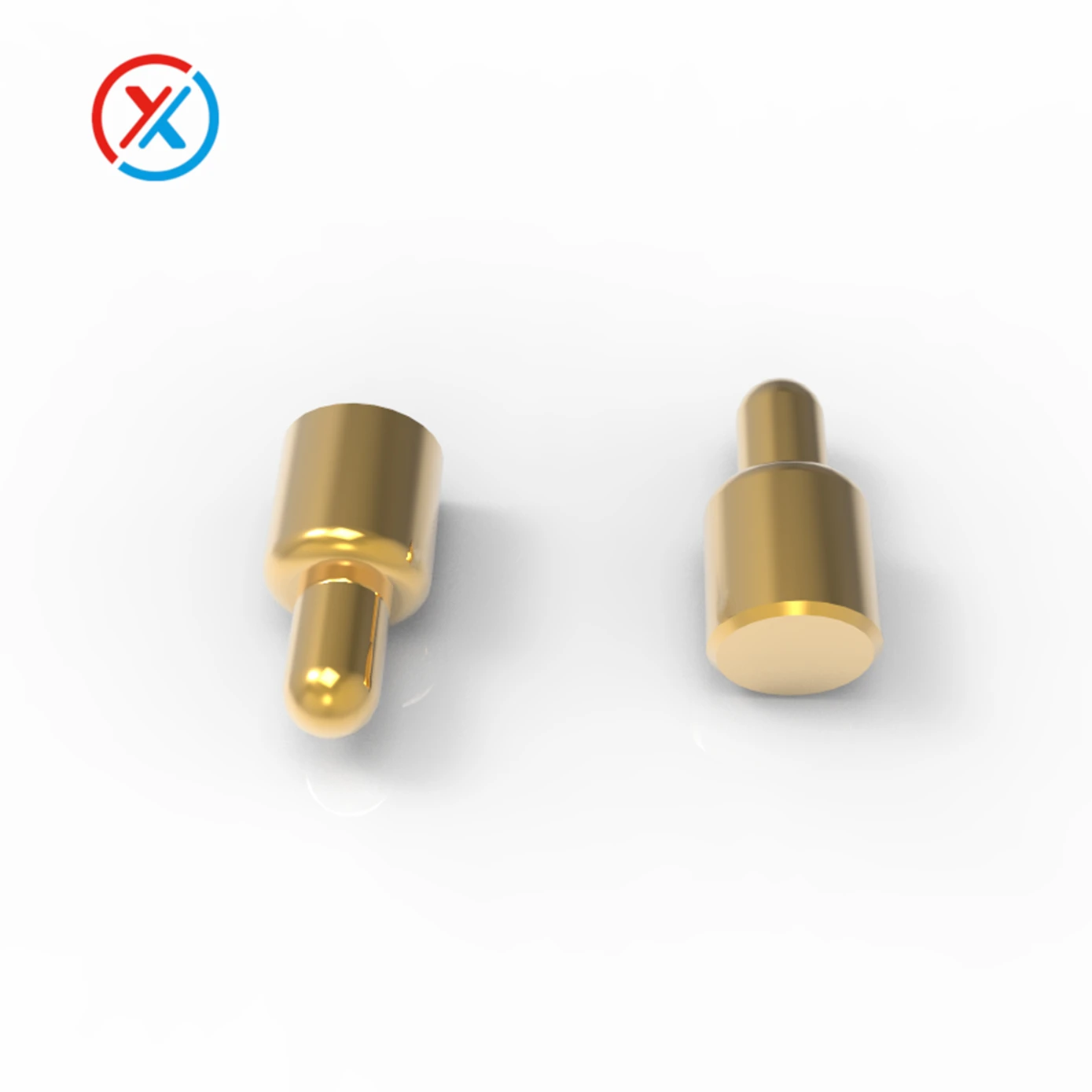
A micro pogo pin typically uses a movable plunger, barrel, and internal spring. The plunger compresses against a mating surface, providing axial compliance within its specified working range.
A stamped spring contact uses a formed metal beam or another resilient geometry to generate contact force. Its shape can combine the conductive path, spring function, mating surface, and termination.
These descriptions identify construction methods, not fixed performance categories.
| Design consideration | Micro pogo pin | Stamped spring contact |
|---|---|---|
| Contact movement | Guided plunger compression, primarily along the pin axis | Deflection determined by the formed contact geometry |
| Mechanical integration | Requires controlled compression, alignment, and retention | Requires controlled engagement, beam deflection, and support |
| Signal performance | Depends on internal geometry, return paths, housing, and transitions | Depends on beam geometry, return paths, housing, and transitions |
| Current capacity | Limited by the complete conductive path and thermal conditions | Limited by the complete conductive path and thermal conditions |
| Durability | Influenced by internal sliding, mating-surface wear, spring behavior, and contamination | Influenced by beam stress, mating-surface wear, relaxation, and contamination |
| Manufacturing economics | Precision machining and assembly can support flexible dimensional customization | Dedicated tooling can support efficient repeat production |
For high-speed signals, the connector must be evaluated as part of a transmission channel. Contact length, conductor spacing, dielectric materials, grounding, shielding, mating pads, and PCB transitions all influence the result.
At a nominal raw data rate of 224 Gb/s, PAM4 carries two bits per symbol, giving a symbol rate of 112 GBd and a Nyquist frequency of 56 GHz. However, evaluating a connector only at 56 GHz is insufficient. Channel behavior beyond Nyquist, resonances, equalization, and noise also affect signal recovery.
The impedance target must come from the intended interface specification. PAM4 describes the modulation format; it does not independently establish an 85-ohm differential impedance requirement.
A meaningful comparison therefore needs matched conditions. The two connector candidates should be evaluated with equivalent reference impedances, measurement boundaries, PCB transitions, and signal assignments. Otherwise, differences attributed to the contacts may actually come from the test boards or fixtures.
Simulation results should be identified as simulations. Measured results should state the sample configuration, working compression, fixture treatment, and frequency range. Useful evidence includes differential insertion loss, return loss, crosstalk, mode conversion, and system-level error performance.
Loss terminology also needs consistent signs. A requirement for no more than 0.5 dB of insertion loss can be expressed as an insertion-loss magnitude of ≤0.5 dB, or an S21 magnitude in decibels of ≥−0.5 dB. Similarly, return loss of ≥15 dB corresponds to an S11 magnitude in decibels of ≤−15 dB. Mixing these conventions can reverse the meaning of a specification.
A short compression interface may help reduce certain discontinuities, but a pogo pin is not automatically free of stubs or resonances. Its mating pads, mounting arrangement, and PCB vias remain part of the signal path.
Current capacity needs a separate assessment. Fine-pitch signal contacts and high-current power contacts may use different dimensions and internal structures, even when both are described as pogo pins. A rating from a larger power contact cannot be transferred to a miniature signal pin.
Stamped contacts also include purpose-designed high-current products. Stamped-and-formed power connector designs demonstrate that the manufacturing method itself does not impose a universal 1–3 A limit.
Resistance and current figures should be checked together. Using P = I²R, a conductive path with 30 mΩ resistance produces:
3 W of resistive heating at 10 A, with a 0.3 V voltage drop.
75 W of resistive heating at 50 A, with a 1.5 V voltage drop.
These calculations do not describe every contact; they show why a resistance limit cannot be combined with an unrelated maximum-current claim to imply low heating.
Current qualification should define ambient temperature, allowable temperature rise, conductor size, working position, and the number of adjacent loaded contacts. Parallel contacts require additional review because manufacturing variation and unequal path resistance can produce uneven current sharing.
An internal ball or biased-plunger structure may improve the intended conductive path in a particular pogo pin. It does not independently guarantee a current rating, continuous contact under every condition, or uniform sharing across an array.
Mechanical reliability is equally application-specific. Pogo pins contain moving interfaces between the plunger and barrel. These surfaces can experience friction, plating wear, and contamination. Axial compression does not eliminate internal wear.
Stamped contacts can incorporate deliberate wiping action to manage surface films. Their durability depends on contact pressure, sliding distance, plating, material condition, and beam stress. Fretting caused by small relative movements can affect either technology.
For a server connection that remains assembled for long periods, retained contact force and resistance during thermal exposure may matter more than an exceptionally high mating-cycle count. A production test socket faces a different duty cycle, with repeated engagement, contamination, and maintenance becoming more prominent.
Compliance should be assessed against the assembled tolerance range. At the largest gap, every contact needs adequate engagement. At the smallest gap, the contact must remain within its permitted deflection or compression. Package warpage and board bending require analysis of the full contact array and clamping structure.
Array force can be substantial. As an illustrative calculation, 2,000 contacts operating at 0.2 N each create a combined force of 400 N. The mounting structure must distribute that load while maintaining alignment and limiting deformation.
Density comparisons should use the complete interface. Nominal pitch alone does not account for ground contacts, shielding, insulation, routing access, mounting features, or the housing. A smaller pitch is useful only when the resulting assembly meets its electrical and mechanical requirements.
For OEM projects requiring a custom compression interface, we can work from customer drawings to develop pogo pin contacts, insulating carriers, mounting features, and mating components. Magnetic connector arrangements and cable terminations can be incorporated where the application calls for them. Samples and small batches provide a basis for checking fit and function; any high-speed claim must then be supported by testing of the proposed assembly.
Selection should remain tied to the connection's role:
Semiconductor test sockets: Prioritize access to the package terminals, electrical measurement requirements, controlled force, cleaning, and contact replacement.
Permanent package interfaces: Evaluate package compatibility, sustained clamping, thermal deformation, power delivery, and channel performance.
Board and backplane connections: Review routing, shielding, retention, assembly tolerances, and service procedures.
External module interfaces: Address the applicable mating interface, electromagnetic containment, grounding, and any required hot-plug sequencing.
Magnetic alignment can assist docking, but spring contacts still require compression force. Magnets alone do not create a zero-force electrical interface or establish hot-plug capability.
Before production approval, compare candidate assemblies against the same acceptance criteria. The review should include signal measurements, resistance and temperature under load, force across the tolerance range, and performance after the relevant mechanical and environmental exposure. Procurement decisions can then reflect verified performance, manufacturing consistency, tooling cost, and service requirements.
1. Are micro pogo pins always better for 224 Gb/s PAM4 connections?
No. Suitability depends on the complete connector and channel design. Compare measured electrical performance under equivalent conditions rather than assigning bandwidth from the contact type.
2. Can a miniature pogo pin carry 10–50 A continuously?
That range cannot be assumed for a miniature contact. The specific design needs a current rating supported by temperature-rise testing, defined installation conditions, and an appropriate resistance limit.
3. Do pogo pins always last longer than stamped spring contacts?
No. Durability depends on materials, plating, contact force, movement, environment, and the acceptance criteria. A mating-cycle rating also does not establish long-term performance while continuously compressed.
4. What should an OEM provide for a custom interconnect review?
Provide mechanical drawings, contact assignments, working height, tolerance limits, electrical loads, and the intended signal interface. Include retention requirements, thermal conditions, service expectations, and the test criteria the finished assembly must meet.


