


Pogo pins suit this type of connection because their plungers compress against mating pads. The spring provides contact pressure and accommodates a defined amount of variation in the assembled height. The dock's housing supports the speaker, guides its position, and prevents excessive compression.
A successful design brings these functions together. The electrical contacts, seating surfaces, enclosure, and charging circuit all need to work within the same mechanical and electrical requirements.
When the speaker is lowered onto the dock, guide features should bring the contacts into alignment before they reach their working compression. A shallow locating recess, a shaped seating surface, or other positioning features can help the user place the speaker correctly without searching for a small charging socket.
For a round speaker, the permitted docking orientation needs particular attention. A circular enclosure does not automatically provide rotation-independent charging. The contact arrangement must maintain the correct power polarity in every allowed position, while the housing should prevent unintended engagement.
Magnets can assist positioning and retention, but they are optional. A dock may rely on the speaker's weight and mechanical seating where these provide sufficient engagement. In either arrangement, the available seating force must accommodate the combined spring force of the contacts and any compressed seals.
The housing should carry the speaker's weight and normal handling loads. The pogo pins need enough compression to establish reliable contact without becoming the structural stops. This is especially important when a user presses down on the speaker, places it at an angle, or operates controls while it is docked.
Charging during playback can make the dock more useful, but this capability depends on the speaker's electronics. The charging and power-management circuits must support simultaneous operation, and the power source must cover the intended playback load as well as battery charging and conversion losses.
A speaker may charge normally while idle yet charge more slowly at high playback volume. If its operating demand exceeds the available input power, the battery may continue supplying part of the load. The product specification should therefore define the expected behavior during playback, rather than treating simultaneous charging as an automatic benefit of the connector.
The dock can also become part of the product's appearance. Its outline, surface finish, and cable exit can follow the speaker enclosure, allowing the device to remain in its usual position while charging. This gives the industrial design team more freedom to place the electrical interface on the underside instead of leaving a charging socket visible on the side.
That freedom still needs to leave room for manufacturing and maintenance. The contacts must remain accessible for inspection and cleaning, and the cable routing should avoid pulling the base out of position.
| Design area | What needs to be established |
|---|---|
| Seating and alignment | How the speaker reaches its final position and which docking orientations are permitted |
| Contact compression | Minimum and maximum compression after accounting for the speaker, dock, PCB, and housing tolerances |
| Contact force | Force at the working position and the total load from all engaged pins |
| Electrical capacity | Continuous current, peak demand, allowable voltage drop, and temperature under load |
| Mating surfaces | Pad dimensions, surface finish, positional tolerance, and expected wear |
| Mechanical support | How the housing carries weight, user pressure, and cable loads |
| Environmental protection | Expected exposure to dust, spills, humidity, and cleaning products |
| Assembly | Contact mounting, soldering access, cable termination, and inspection requirements |
Material and plating choices affect how the interface performs after repeated docking. Copper-alloy plungers and barrels with a suitable plated finish are common options. The spring material is selected for its required force, working travel, temperature exposure, and durability.
Gold over a suitable nickel underlayer is one possible contact finish. Its effectiveness depends on the coating specification, coverage, adhesion, surface condition, and mating material. A proprietary finish name alone does not establish wear resistance or service life. The specification should identify the required performance and the tests used to verify it.
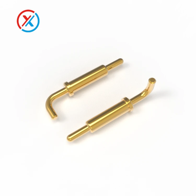
The mating pads deserve the same attention as the pogo pins. A durable pin finish cannot compensate for an unsuitable opposing surface. Pad size should accommodate the expected positioning variation, while the finish should suit the contact pressure, movement, and environment.
Water resistance requires a separate review of the assembled product. Contact seals, housing joints, cable entries, and the installation method all affect protection. The requirements should distinguish between the speaker while docked, the speaker while undocked, and the powered charging base.
A spill-resistant speaker does not automatically make its charging dock equally protected. Recesses around the contacts should be reviewed for trapped liquid and debris, and exposed power contacts need appropriate electrical protection. Any claimed protection level should be supported by testing in the specified assembly condition.
Where an existing connector does not fit the speaker's shape or available space, we can develop the interface from customer drawings. This can include custom pogo pin dimensions, insulating carriers, mating pads, magnet placement, mounting features, and cable terminations. Coordinating these parts allows the contact travel and electrical connections to be reviewed alongside the enclosure. Sample or small-batch assemblies can then be evaluated in the intended speaker and dock.
Prototype testing should include repeated placement, removal, and operation at the permitted docking orientations. Check that all pins engage, move smoothly, and return correctly. Measure voltage drop and temperature under the intended charging load, including playback conditions where the product supports them.
Durability evaluation should also reflect how the speaker will be used. Relevant conditions may include prolonged time on the dock, vibration during playback, cable movement, and the specified environmental exposure. After testing, inspect the mating surfaces and reassess contact resistance, spring force, and charging stability. These results provide a practical basis for finalizing the drawings and production acceptance criteria.
1. Why use pogo pins in a smart speaker charging dock?
Pogo pins establish contact when the speaker is placed onto mating pads. Their working travel accommodates specified height variation, while the dock provides alignment and support. This can make charging convenient without requiring the user to connect a separate plug each time.
2. Can the speaker play music while charging through pogo pins?
Yes, when the speaker's power-management circuit and power source support simultaneous playback and charging. The connector and wiring must also carry the required load within the specified voltage-drop and temperature limits.
3. Does a pogo pin charging dock need magnets?
No. Magnets can help with alignment and retention, but a suitable mechanical seat may work with the speaker's weight. The chosen arrangement must maintain the required contact compression during normal use.
4. What information is needed for a custom speaker charging dock?
Provide the speaker and dock drawings, available installation space, permitted docking orientations, charging requirements, and preferred cable connection. Expected usage, environmental exposure, surface finishes, and production quantities help define the contact assembly and sample evaluation.


