


This arrangement can be useful when a power connection needs low resistance, manageable insertion force, and repeated mating. Its suitability depends on the complete connector design and operating conditions. Current capacity, temperature rise, and mating force should therefore be specified together.
For charging equipment, the practical challenge is carrying the required current without excessive voltage drop, heating, or deterioration over time. A connector that performs well when new must also maintain acceptable contact pressure and electrical resistance after repeated use.
The crown spring arrangement distributes contact around the mating pin. Each engaged finger contributes to the interface, while its elastic deflection accommodates the specified fit between the pin and socket. The number of fingers alone does not determine performance: their geometry, material, surface finish, and contact force all matter.
Current also passes through the connector body, terminations, and associated conductors. Poor cable termination or an undersized conductive section can become a heat source even when the spring interface performs correctly. The rating must apply to the assembled power path.
Resistance becomes increasingly important as current rises. Resistive heating follows P = I²R, so doubling the current produces four times the heat at the same resistance. For example, a connection with 1 milliohm of resistance dissipates 10 watts at 100 amps. This illustrates why small resistance changes can have a significant thermal effect in a high-current assembly.
Temperature-rise testing should use the intended conductor size, mounting arrangement, ambient conditions, and electrical load. Nearby loaded contacts and enclosed housings can influence heat dissipation. A current value measured under one installation condition may require reassessment when the connector is placed inside the finished equipment.
Low insertion force is another useful design objective, particularly for equipment that docks automatically or requires frequent manual connection. Crown spring geometry can distribute the required elastic deflection across multiple contact elements. A suitable mating profile helps guide the pin into the socket without damaging the spring fingers.
Insertion force and electrical contact pressure are related, but they are not interchangeable measurements. Friction, plating, spring geometry, and dimensional fit all affect the force needed to mate the connector. The design needs sufficient contact pressure while keeping insertion and withdrawal forces within the equipment's operating limits.
Mechanical retention should also be defined separately. A connector that mates easily may require a latch, guided docking mechanism, or other support to remain seated during vibration or cable movement. The surrounding structure should control misalignment and prevent the contact insert from carrying unintended sideways loads.
Material selection involves a balance between conductivity and mechanical performance. The main conductive body needs suitable electrical and thermal properties, while the spring insert must retain its contact force through repeated deflection and the expected temperature exposure.
The surface finish must suit the mating materials, environment, and wear conditions. Silver, gold, and other contact finishes serve different requirements; none establishes a current rating by itself. Coating thickness, underlayers, adhesion, coverage, and the condition of the opposing contact should be defined as part of the specification.
Manufacturing dimensions directly influence this balance. Mating-pin diameter, spring-insert geometry, alignment, and surface finish affect both contact pressure and insertion force. Inspection should address the finished parts, including the dimensional changes introduced by plating and assembly.
For custom charging interfaces, we can work from customer drawings to coordinate precision-machined contact parts, insulating carriers, mounting features, and cable terminations. Where the equipment also requires pogo pin contacts or magnetic docking, these can be developed around the same mechanical layout. Sample assemblies allow fit, contact engagement, and electrical performance to be evaluated before production requirements are finalized.
Crown spring power contacts can be considered across several applications, with different priorities in each case.
| Application | Possible connection function | Main design considerations |
|---|---|---|
| Warehouse robots and mobile equipment | Repeated connection to a charging station | Docking alignment, mating cycles, contamination, and reliable seating |
| Battery charging equipment | Detachable connection between the charger and battery system | Continuous current, temperature rise, polarity, and engagement detection |
| Industrial power modules | Removable power connection within equipment | Installation space, mechanical retention, terminal design, and service access |
| Transport equipment | Power interfaces in specified vehicle subsystems | Vibration, temperature variation, environmental exposure, and application qualification |
| Specialized instruments and equipment | Compact power connections with controlled mating force | Electrical requirements, materials, cleaning conditions, and customer acceptance criteria |
A charging connector also has to operate within the equipment's electrical control strategy. Contact engagement detection, power sequencing, and the behavior during disconnection need to be addressed by the complete system. A continuous-current rating does not establish that a connector can repeatedly make or break that current under load.
For automated docking, mechanical and electrical development should proceed together. The equipment must approach within the permitted alignment range, reach the intended engagement depth, and remain seated while charging. Control contacts or other detection methods can be incorporated where the system requires confirmation of engagement.
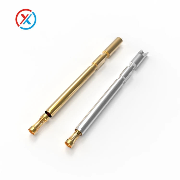
Before approving a design, establish measurable acceptance criteria. These should cover initial resistance, resistance after durability testing, mating and withdrawal forces, temperature rise, insulation, and the condition of the contact surfaces.
Representative assemblies should then be evaluated with the intended cables, terminals, housing, and mounting hardware. Repeated mating and relevant environmental exposure should be followed by electrical and mechanical checks. This provides a more useful basis for selection than an isolated maximum-current figure or an unsupported claim of market-leading performance.
1. How much current can a crown spring connector carry?
There is no universal rating for the design. Capacity depends on contact geometry, materials, terminations, conductor size, ambient temperature, and allowable temperature rise. Use the rating and test conditions for the specific assembled connector.
2. Does low insertion force mean poor electrical contact?
Not necessarily. Spring geometry and the mating profile can provide suitable contact pressure with manageable insertion force. Both force and electrical resistance should be measured across the specified dimensional tolerances and service conditions.
3. Is a crown spring connector the same as a pogo pin connector?
They use different contact arrangements. A typical crown spring socket has resilient fingers around a mating pin. A pogo pin uses a moving plunger within a barrel, supported by an internal spring. Selection depends on the required mating action, available space, and electrical performance.
4. What information is needed for a custom high-current connector?
Provide the mating drawings, installation space, continuous and peak currents, operating voltage, conductor size, and temperature limits. Required mating force, connection cycles, environmental exposure, and docking or retention features help define the design and validation plan.


