


The main opportunities are interfaces that benefit from controlled contact pressure, axial tolerance accommodation, and convenient assembly or removal. Achieving reliable operation requires the contacts, mounting structure, electrical circuit, and environmental protection to work together.
The application must be defined before choosing a connector. A rear-seat tablet dock has different requirements from an internal module connection. Neither establishes suitability for a traction battery, motor drive, or vehicle fast-charging circuit.
High-current capability and high-voltage suitability are separate requirements. A pogo pin designed for a low-voltage power interface should not be presented as a traction-power solution without evidence covering that specific application.
Potential vehicle-electronics applications include:
| Application | Possible interface function | Main design priorities |
|---|---|---|
| Rear-seat display or tablet dock | Charging, identification, and supported communication | Device support, retention, alignment, and vibration performance |
| Center-console accessory dock | Detachable power and control connection | User handling, contact protection, and electrical compatibility |
| Removable interior module | Power or signals between assembled components | Installed height, working compression, mounting, and service access |
| Selected audio-related module | Power, control, or audio connections according to the circuit | Electrical load, continuity, contact resistance, and mechanical retention |
These are design possibilities rather than evidence that every vehicle uses the same connection method. Each interface needs evaluation against the equipment manufacturer's requirements.
Vehicle motion makes mechanical support particularly important. The internal spring helps maintain contact pressure within the pin's working travel, but the surrounding structure must keep the mating parts aligned and retained.
Guides establish position, stops control engagement depth, and suitable fasteners or retention features maintain the assembled relationship. The pins should not carry the weight of a display or absorb substantial sideways loads.
Working compression must remain acceptable across dimensional variation in the contacts, carrier, PCB, enclosure, and mating component. Too little compression can leave inadequate force. Too much can increase stress or damage the mechanism.
Vibration can introduce small relative movements even when the assembly remains attached. These movements may affect electrical continuity and cause wear at the mating surfaces or inside the pin. A spring-loaded structure therefore needs testing in the representative installation.
The acceptance criteria should identify what constitutes an unacceptable interruption. Monitoring the electrical path during vibration or shock provides information that an initial static resistance measurement cannot.
Magnetic retention can make a removable accessory easier to dock. Its suitability depends on the complete assembly, including device mass, mounting direction, cable loads, and the force required to compress the contacts.
Magnets should work with mechanical guidance and support. A magnetic holding-force measurement taken in one pull direction does not establish performance under every vehicle movement or handling condition.
Electrical loading requires similar attention. The full conductive path includes the mating pads, plunger-to-barrel interfaces, terminations, PCB connections, and any cable conductors. Resistance along that path contributes to voltage drop and heat.
A current rating should identify the working compression, ambient temperature, installation, and loading conditions. Contacts evaluated individually may behave differently when several neighboring positions carry current inside an enclosure.
Where contacts operate in parallel, current sharing depends on the resistance of each path. Differences in engagement, conductor routing, or termination quality can produce unequal loading. Adding pins does not automatically multiply the usable current rating by the pin count.
For an audio-related module, the connector carries the current required by its circuit. It does not regulate or precisely distribute that current. Power, control, and speaker-output connections also have different requirements, so the intended function must be clear.
Signal capability needs its own specification. A low-resistance power connection does not establish suitability for high-speed video or data. Contact geometry, ground arrangement, PCB transitions, and wiring must support the selected interface.
Compact packaging is another reason to consider pogo pins. Contacts can be arranged around available mounting space, and their axial travel can accommodate a defined variation in the distance between mating parts.
The complete installation still occupies space. Barrels, working travel, carriers, mating pads, guides, and retention features must all be included in the comparison with other connector types.
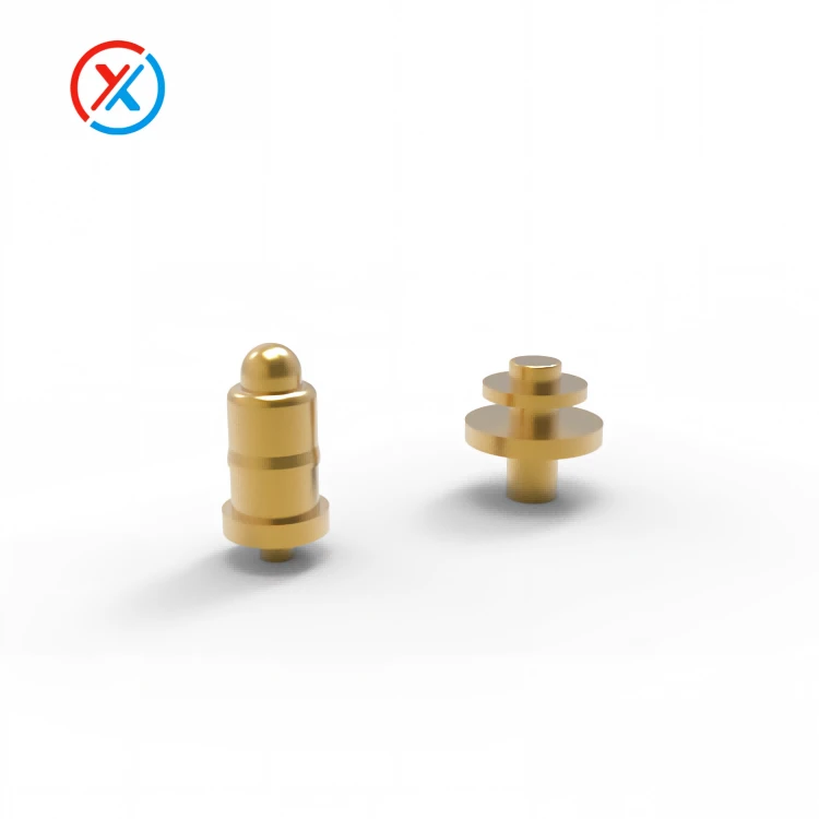
A dense contact array also creates a combined compression load. The PCB and housing need sufficient support to maintain the intended engagement without excessive deflection. Reducing pitch should therefore be assessed alongside electrical spacing, manufacturing tolerances, and assembly stiffness.
Materials and finishes should reflect the connector's location. An interior accessory interface may encounter handling, cleaning residues, condensation, or spilled liquid. Other installation areas may have different temperature and contamination conditions.
Contact plating can help manage corrosion and wear, but its effectiveness depends on the coating system, mating finish, contact force, and exposure. Sealing and protective geometry address separate moisture and contamination paths.
Durability requirements should include both mating cycles and time spent engaged. A serviceable module may experience relatively few removals while remaining compressed through repeated temperature changes.
For drawing-based projects, XINTENG can coordinate the contacts, insulating carrier, mounting features, mating parts, and cable or PCB terminations. Samples or small-batch assemblies can be developed around the available space and evaluated before the production configuration is approved.
A useful validation plan may include:
Contact resistance and voltage drop at the specified installed position.
Temperature rise under representative electrical loading.
Contact force and reliable plunger movement.
Continuity during relevant vibration and shock exposure.
Electrical and mechanical checks after cycling, temperature exposure, or contamination testing.
Approval should remain tied to the tested materials, dimensions, finishes, and assembly configuration. Production drawings, inspection criteria, material records, and change-control requirements help preserve that relationship.
1. Can ordinary pogo pins carry an electric vehicle's main traction power?
That capability cannot be assumed. Traction circuits require application-specific electrical, thermal, insulation, mechanical, and protection validation. A low-voltage contact rating does not establish suitability.
2. Do pogo pin connectors automatically resist vehicle vibration?
No. Reliable engagement depends on the contact design, working compression, alignment, retention, and structural support. The assembled interface needs verification under the required conditions.
3. Can pogo pins support both charging and display data?
They can when the contacts and complete electrical channel support both functions. Current capacity and communication performance require separate evaluation, followed by testing in the intended operating configuration.
4. What information is needed for a custom vehicle-electronics connector?
Provide installation drawings, electrical requirements, contact assignments, working compression, mounting details, and operating conditions. Include retention needs, expected service cycles, and the customer's validation and approval requirements.


