


The benefit is most relevant where the design needs controlled contact force, axial compliance, or repeated separation. Suitability depends on the electrical function, available space, mounting arrangement, and expected operating conditions.
A phone contains several types of interconnects. Flexible circuits, board-to-board connectors, coaxial connections, stamped spring contacts, and pogo pins serve different purposes. Selecting among them requires consideration of the complete interface.
Stamped spring contacts remain suitable for compact products and can offer a low-profile arrangement. Pogo pins occupy space for the barrel, spring, plunger, and working travel. Their axial movement may fit one layout well, while a stamped contact's geometry may better suit another.
Pogo pins are not automatically smaller, more durable, or more waterproof than stamped contacts. Those comparisons need to be made between specific assemblies under equivalent requirements.
For phone-related applications, several interfaces may justify evaluating a pogo pin design:
| Interface | Potential use of pogo pins | Main design considerations |
|---|---|---|
| Dedicated charging dock | Contact-based power connection as the phone seats in a cradle | Current capacity, alignment, retention, and exposed-contact protection |
| Removable accessory | Power, identification, or communication between the phone and accessory | Contact assignments, installed height, mechanical support, and compatibility |
| Selected internal connections | Power, ground, or other suitable electrical connections between assembled parts | Contact force, tolerance variation, electrical behavior, and retention |
| Antenna or RF interface | A pressure-contact transition where the complete RF design supports it | Geometry, return path, impedance, and measured RF performance |
| Production test fixture | Temporary access to designated test pads | Positioning, probe travel, contamination, wear, and replacement access |
Camera and display connections require particular care. Their high-speed interfaces often use dedicated flexible-circuit or board-to-board connections. A pogo pin arrangement would need to meet the same channel requirements before it could be considered a substitute.
Low DC contact resistance alone does not establish high-speed performance. The contacts, ground arrangement, PCB transitions, and surrounding geometry influence signal transmission.
The same principle applies to antenna connections. A short contact may be mechanically convenient, but RF suitability depends on the complete signal and return paths. It cannot be inferred from the pin's size or gold finish alone.
Mechanical design starts with the assembled position. The relevant dimension is the distance between the mounted contact and its mating surface, including the tolerances of the PCB, housing, carrier, and mating component.
At that position, the plunger must reach its specified working compression. Insufficient compression can leave inadequate contact force, while excessive compression can increase stress or damage the mechanism.
The housing should establish alignment and support the components. Pogo pins accommodate a defined amount of movement along their compression axis; they should not be expected to locate loosely supported parts or carry substantial sideways loads.
This distinction matters during a drop or impact. The internal spring provides compliance, but continuity also depends on the enclosure, fasteners, supports, and movement of the connected components. Verification should use a representative assembly rather than an isolated contact.
For an external charging dock, a practical arrangement places fixed pads on the phone and spring-loaded contacts in the dock. The device can present an accessible contact surface while the charger contains the moving components.
Guides establish the docking position, and a suitable retention feature keeps the phone seated. Magnets can assist these functions where appropriate, but the dock must still support the phone and prevent excessive loading of the pins.
The electrical design should identify the required charging voltage, current, and any identification or communication functions. A magnetic attachment or a particular pin count does not establish fast-charging compatibility.
Current capacity depends on the complete supply and return paths, including the mating pads, internal interfaces, terminations, and PCB connections. Resistance and temperature rise should be evaluated under the intended load and installation conditions.
Materials and finishes affect long-term performance. Copper-alloy plungers and barrels can provide a suitable conductive structure, while the spring material is selected for its mechanical requirements. Contact plating helps manage surface stability, corrosion, and wear.
Gold plating can support reliable contact, but its performance depends on thickness, adhesion, porosity, hardness, and the layers beneath it. The mating-pad finish also needs to be specified.
Repeated compression creates movement inside the pin, and the external contact surface may experience wear during engagement or small movements after assembly. A life claim should therefore include the working travel, mating action, environment, and electrical and mechanical acceptance criteria.
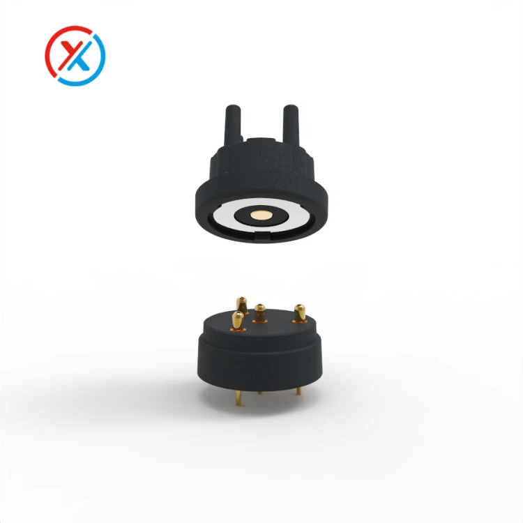
Water protection requires separate engineering. Sealing around a fixed contact can prevent ingress at that interface, but the moving clearance between a plunger and barrel can present another moisture path.
A connector's protective design does not establish the water resistance of the entire phone. Housing joints, seals, mounting interfaces, and other openings must work together. Connected and disconnected conditions may also require different evaluation.
For custom projects, XINTENG can work from phone, accessory, or fixture drawings to coordinate contact dimensions, carriers, mating pads, mounting features, and terminations. Non-standard parts can be developed around the available space, with samples or small batches used to evaluate fit and performance.
Useful validation includes dimensional checks, force versus travel, electrical resistance, temperature under load, and reliable plunger return. Repeated mating and relevant environmental or mechanical exposure should be followed by functional checks.
The approved drawings should retain the dimensions, materials, finishes, and inspection limits used during evaluation so that subsequent changes can be assessed against the same requirements.
1. Are pogo pins better than stamped spring contacts for mobile phones?
Neither is universally better. Compare installed height, lateral space, working travel, electrical requirements, assembly method, durability, and cost for the specific interface.
2. Can pogo pins connect a phone's camera or antenna?
Only when the complete connection meets the relevant signal requirements. Camera data and RF antenna interfaces need dedicated electrical evaluation; mechanical fit and low DC resistance are insufficient.
3. Can pogo pin contacts be integrated into a waterproof phone?
They can form part of a sealed device design. Protection depends on the complete contact mounting and enclosure arrangement, including any exposed moving interfaces.
4. What information is needed for a custom phone-related pogo pin connector?
Provide assembly drawings, available space, contact assignments, electrical requirements, working compression, and environmental conditions. Include the mating surface, mounting method, expected connection cycles, and required test criteria.


