





Magnetic Pogo Pin Spacing 2.0mm

Magnetic Pogo Pin Spacing 2.0mm suppliers

Magnetic Pogo Pin Spacing 2.0mm factory

Magnetic Pogo Pin Spacing 2.0mm best

Magnetic Pogo Pin Spacing 2.0mm high quality

Magnetic Pogo Pin Spacing 2.0mm price

Magnetic Pogo Pin Spacing 2.0mm price

Magnetic Pogo Pin Spacing 2.0mm price

Magnetic Pogo Pin Spacing 2.0mm price

Magnetic Pogo Pin Spacing 2.0mm suppliers
Magnetic Pogo Pin Spacing 2.0mm
Dongguan Xinteng Electronics Co., Ltd. is one of the most reliable manufacturers and suppliers of magnetic pogo pin spacing 2.0mm in China, featured by quality products and good service. Welcome to wholesale bulk durable magnetic pogo pin spacing 2.0mm in stock here from our factory. Also, customized service and OEM&ODM service are available.
Details
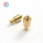
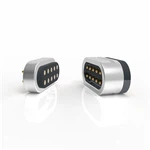
The Magnetic Pogo Pin SM-800 places five contacts in a single row within an elongated housing. Its compact geometry can be evaluated for detachable interfaces where the available mounting space is limited. The two parts differ in length, width and body height, so both drawings should be reviewed during enclosure design.
Product Parameters
|
Product model |
SM-800-5 PIN |
|
Mechanical |
|
|
Contact force |
80g±20g at 0.8m working stroke Full stroke 1.0mm |
|
Life test |
10,000 cycles |
|
Adsorption capacity test |
The parent docking adsorption is 600g±20% |
|
Electrical |
|
|
Rated voltage |
DC 12V |
|
Rated current |
3A Max |
|
Contact resistance of spring pin |
50 milliohm Max |
|
Materials |
|
| Operating temperature |
-25℃ to +80℃ |
|
Pogo pin |
Gold-plated brass |
|
Housing |
HTN |
|
Magnet |
N52 |
|
Packing |
PE bag / reel packing |
|
Material and coating conform to ROHS and REACH standards |
|
Mechanical Specifications
| Parameter | 14.15 mm housing drawing | 13.00 mm housing drawing |
|---|---|---|
| Contact count | 5 | 5 |
| Contact pitch shown | 2.00 mm | 2.00 mm |
| Overall housing length | 14.15 mm | 13.00 mm |
| Housing width shown | 5.95 mm | 4.80 mm |
| Body height shown excluding rear tails | 5.10 mm | 3.50 mm |
| Rear tail projection shown | 1.50 mm | 1.50 mm |
| Terminal diameter shown | 0.60 mm | 0.60 mm |
These are individual-part dimensions, not the height or envelope of the assembled pair. Request the confirmed PCB footprint and mating dimensions for your selected configuration before releasing production files.


Designing a Compact Mating Interface
Check the connector opening, PCB setback and space behind each housing. The larger outline should not be reused as the cutout for the smaller part. Allow the mating faces to reach the intended operating position while keeping the surrounding enclosure clear of the connection area.
Specify the orientation of the two parts and identify all five circuit connections. Matching contact pitch is one part of compatibility; the housing profile, mating position and magnetic arrangement also need to correspond.
application
1. Consumer Electronics
Bluetooth headsets and charging cases, smart speakers, handheld electronic devices, game controllers, e-readers, portable printers, small digital products, smart remote controls
2. Smart Wearables
Smartwatches, smart bands, GPS sports devices, smart ring charging accessories, sports monitoring devices, wearable health monitoring devices
3. Medical and Health Electronics
Portable monitoring devices, home health devices, electronic testing instruments, detachable sensor modules, charging bases, handheld medical electronic devices
4. Smart Home
Smart door locks, smart sensors, wireless camera equipment, smart control panels, smart lighting modules, robot vacuum accessories, smart home control terminals
5. E-bikes and Smart Cycling Equipment
Display connections, controller interfaces, GPS modules, bike lights, smart lock modules, sensor modules, detachable control panels, charging or auxiliary power interfaces
6. Industrial Automation Equipment
Industrial handheld terminals, data collectors, barcode scanners, industrial inspection equipment, modular control equipment, sensor modules, equipment maintenance interfaces
7. Robotics and Unmanned Equipment
Service robots, educational robots, AGV accessory modules, unmanned equipment sensors, detachable cameras, battery accessories, automatic charging bases
8. Testing Equipment and Charging Bases
Product test fixtures, burn-in testing equipment, firmware programming interfaces, repair interfaces, display stands, docking stations, charging docks
9. Automotive and In-vehicle Electronic Accessories
In-vehicle display accessories, detachable control modules, dashcam accessories, in-vehicle charging mounts, in-vehicle electronic modules

Custom Magnetic Connectors – OEM/ODM
1. Magnetic connector shape and structure: Round, square, rectangular, racetrack-shaped, etc.
2. Pogo pin cable material: PVC, TPE, silicone, etc.
3. Pogo pin cable shape: Round, braided, flat, etc.
4. Waterproof rating: Up to IP68.
5. Magnetic force: 150g–3000g.
6. Rated voltage/current: ≤ 120V, ≤ 40A.
7. Connection orientation: 90°, 180°, or other angles.
8. Interface type: USB 2.0/3.0, HDMI, RJ45, D-SUB, pin headers/sockets, DC jacks, etc.
9. Receptacle (female end) mounting method: DIP (through-hole), 90° right-angle, wire soldering, overmolding, etc.
10. Receptacle positioning method: Grooves/tabs, sealing rings, snap-locks, positioning tabs, locating posts, in-mold injection molding.

Our Advantages
- China's second manufacturer to develop 1.27mm pitch pogo pin connectors
- China's first supplier of non-invasive EEG sensor connection modules
- Factory capable of mass-producing 40A high-current pogo pins
- Manufacturer achieving 1 million cycles of compression mechanical life
- China's professional supplier of charging connection modules for medical, consumer electronics, and specialized industries
Solution
Xinteng Electronics focuses on the R&D and manufacturing of high-reliability magnetic pogo pins, meeting diverse industry requirements such as low impedance, high current, long lifespan, and lateral contact. we provide customers with the safest and most reliable product solutions. Currently, we offer over 2000 solutions to global customers and have applied for over 100 patents. Xinteng products cover consumer electronics, automotive systems, wearable devices, and medical devices.

FAQ
Hot Tags: magnetic pogo pin spacing 2.0mm, China magnetic pogo pin spacing 2.0mm manufacturers, suppliers, factory
You Might Also Like


Send Inquiry