





Spring Pogo Pin | Custom & OEM
Dongguan Xinteng Electronics Co., Ltd. is one of the most reliable manufacturers and suppliers of spring pogo pin | custom & oem in China, featured by quality products and good service. Welcome to wholesale bulk durable spring pogo pin | custom & oem in stock here from our factory. Also, customized service and OEM&ODM service are available.
describe
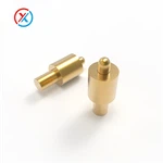
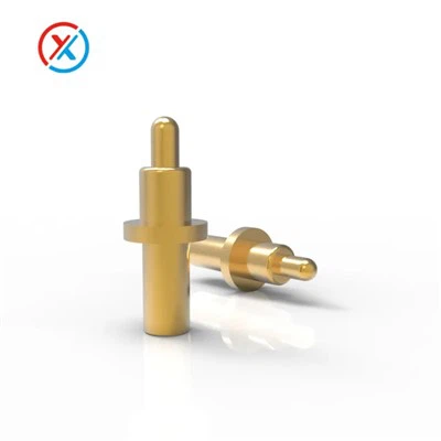
Spring Pogo Pin is a three-piece spring pogo pin consisting of a stainless steel spring, a brass barrel (tube), and a brass plunger. The plunger compresses against an internal spring to make electrical contact with a mating pad, socket, or surface, then returns to its resting position when the mating load is released.
The DIP tail pin at the base seats into a PCB through-hole, allowing the part to be wave-soldered or hand-soldered in place. Once mounted, the spring loaded contact faces outward, ready to mate with a charging pad, module interface, or test point.
parameters
| Product model | RG-1750 |
| Pin Material | Brass / BeCu |
| Plating | Gold, silver, or nickel plating - selected by application environment |
| Contact Resistance | ≤ 50mΩ |
| Current / Voltage | 3A DC 12V |
| Salt spray | 48H |
| Mating Cycles | 10.000 |
| Contact force | 70g ±20g at 1. Omm working stroke Full stroke 1. 4mm |
| Sample Lead Time | 2 to 5 working days |
| Packing | PE bag / reel packing |
| RoHS and REACH certification | |
Products Description
Dongguan Xinteng Electronics Co., Ltd. is one of the top five pogo pin manufacturers in China. It not only offers 500 standard spring pogo pins for customers to choose from, but also supports customization services (ODM/OEM).


Performance Verification
We conduct environmental, electrical, and mechanical performance tests on spring pogo pins and can provide test reports upon request. The following are some of the test reports we can provide, including but not limited to...
- Contact Impedance Test Report
Measures contact resistance at rated mating force across a sample population. The ≤50mΩ specification applies to initial contact conditions; the test report includes distribution data across the sample batch.
- Life Test Report
10,000 compression cycles are applied under controlled conditions, with contact resistance measured at defined intervals (typically every 1,000 cycles for the first 5,000, then at completion). The rated specification must be maintained through the full cycle count. This is the primary test that validates the plating thickness and spring material selection for this spring loaded pogo pin.
- Salt Spray Test Report
48-hour exposure per ASTM B117 (or equivalent). Passes without pitting, delamination, or measurable change in contact resistance at the external mating surface. This rating covers most indoor-ambient and light-industrial operating environments. Products intended for prolonged outdoor exposure or marine environments should discuss application conditions with the engineering team before selection.

Website display is limited; please contact customer service for more products and drawings.
Application Scenarios for Spring Pogo Pins
- Wearable Devices & Smartwatches
The 7.5mm length and 1.50mm barrel diameter fit within the housing constraints of smartwatch charging cradles and fitness tracker docking contacts. At 3A, this spring contact pin handles the current requirements of modern wearable fast-charge protocols without thermal issues at the contact interface.
- IoT Modules & Embedded Systems
Board-to-board spring contact connections in IoT gateways allow modules to be replaced in the field without reflowing solder joints. A row of spring loaded pogo pins on a base PCB mates with pads on a swappable module, making the interface both separable and reliable at low cycle counts.
- In-Circuit Test (ICT) & Functional Test Fixtures
10,000-cycle life is appropriate for lower-volume test jigs where a fixture contacts a few hundred boards per day. The spring loaded test pin format - DIP-mounted to a fixture board, spring tip contacting the unit under test - is a standard approach for single-sided access to test points.
- Portable Medical Equipment
The -40°C to +105°C operating range and RoHS/REACH compliance support use in equipment that sees sterilization cycles or wide ambient temperature variation. The defined contact force (70g ±20g) is consistent enough that connection integrity is predictable across manufacturing tolerances.
- Battery Management & Charging Interfaces
At DC 12V / 3A, this spring pogo pin handles data communication pins and moderate charging lines in battery pack assemblies. For power pins above 3A, custom versions with larger barrel diameters are the appropriate path (see below).

Mounting & PCB Design Notes
A few points that save engineering time before layout is finalized:
Working stroke is a hard limit, not a guideline. The drawing notes explicitly warn against compressing this spring pogo pin beyond the 1.0mm working stroke. The 1.4mm full stroke is a mechanical hard stop - the spring contacts the barrel wall and cannot travel further. Repeated contact at the hard stop permanently alters spring rate and contact force, changing the electrical behavior of the connection in ways that are not visible externally and will not appear until contact resistance degrades.
Design your housing or guide plate so the mating surface can only compress the plunger to 0.7–1.0mm. This gives positive contact without approaching the hard stop.
Pad size for the mating surface. The 0.80mm plunger head diameter suggests a mating pad of 1.0–1.5mm diameter for reliable landing. Smaller pads risk miss-contact under positional tolerance stacks; larger pads are fine electrically.
PCB through-hole recommendation. For the Φ0.50mm tail pin, finish hole diameter in the range of 0.65–0.75mm suits most standard FR4 processes. Leave adequate annular ring for solder fill - 0.25mm minimum ring width is a reasonable floor.
Orientation tolerance. The drawing specifies ±2° angular tolerance for features in the 0°–6° range. For automated press-fit or pick-and-place insertion, clearance for this tolerance in the guide housing prevents binding during assembly.

Custom Spring Pogo Pin Configurations
Current Rating: Custom barrel diameters and plating combinations extend current handling from 3A up to 60A for power-hungry applications. High-current spring pogo pin designs require a different tube geometry and heavier base material - contact the engineering team with your current, voltage, and thermal context.
Overall Length & Working Stroke: Housing geometry sometimes demands a shorter or longer pin than the 7.5mm standard. Custom lengths can be specified; note that changing overall length affects stroke and contact force, which need to be re-validated for each custom configuration.
Plating Type & Thickness: Gold, silver, or nickel plating is available. Silver reduces contact resistance at initial contact but requires more careful handling to avoid tarnish in humid environments. Nickel is a cost-effective option where cycle counts are low and the operating environment is well-controlled.
Mounting Style: DIP through-hole is standard for the RG-1750-11P, but SMT (surface mount), press-fit, and threaded-barrel variants of the spring contact pin are available in custom configurations.
Plunger Tip Geometry: Crown, serrated, pointed, and flat tip options suit different mating surface conditions. A crown or serrated tip cuts through light surface oxidation on gold-free pads; a flat tip maximizes contact area on clean gold or nickel surfaces.
Sample lead time for custom spring loaded pogo pin configurations: 7–15 business days. Bulk lead time: 20 business days. Minimum order quantity for standard parts: 1,000 pieces.

Frequently Asked Questions
What is the difference between working stroke and full stroke on a spring pogo pin?
Working stroke (1.0mm on the RG-1750-11P) is the designed travel range during normal operation - the distance over which the spring pogo pin delivers its rated contact force and electrical performance. Full stroke (1.4mm) is the absolute mechanical limit where the plunger physically cannot travel further. Using working stroke as the operating point gives a margin that protects the spring and ensures contact force stays within the specified 70g ±20g range. Designing to full stroke will cause the spring to bottom out with every mating cycle and shorten service life.
Can the RG-1750-11P carry more than 3A?
The 3A rating is the continuous DC maximum for the standard configuration. This rating reflects the combination of contact resistance (≤50mΩ), contact area, and thermal path through the brass barrel and PCB pad. Sustained current above 3A will produce resistive heating at the contact interface that accelerates plating wear and can cause intermittent contact failures over time. Custom spring pogo pin designs with larger barrel diameters are available for 5A, 10A, or higher current requirements.
What PCB hole size should I use for the tail pin?
The tail pin is Φ0.50mm. A finished hole diameter of 0.65–0.75mm is the standard recommendation for this tail size on FR4 boards with HASL or ENIG surface finish. The actual value depends on your PCB fabricator's plating process - confirm the drill-to-finish-hole compensation factor with them before releasing the board file.
Is this spring pogo pin compatible with nickel-plated mating pads?
Yes. Gold-to-nickel contact is a common pairing in PCB-level connectors. Contact resistance at a gold-plated plunger to nickel-plated pad interface will typically be slightly higher than gold-to-gold, and the nickel surface will show wear marks faster. If your application uses nickel pads and requires ≤50mΩ, test contact resistance after 1,000 cycles under your actual mating conditions before locking in the design.
What is the minimum order quantity, and are samples available?
Standard minimum order quantity is 1,000 pieces for the RG-1750-11P spring pogo pin. Engineering samples (5–10 pieces) are available for evaluation and are typically shipped within 2–7 working days. Samples for custom configurations ship in 7–15 working days depending on tooling requirements.
Does this spring pogo pin meet RoHS and REACH requirements?
Yes. The material and surface coatings for the RG-1750-11P - SUS304 stainless steel spring, brass C6801 barrel and plunger, gold plating - comply with both RoHS (Restriction of Hazardous Substances) and REACH (Registration, Evaluation, Authorisation and Restriction of Chemicals) standards. Test reports are available for download or on request.
Hot Tags: spring pogo pin | custom & oem, China spring pogo pin | custom & oem manufacturers, suppliers, factory, 1mm Pogo Pin, contact pins, micro pogo pins, pogo pin 1 27 mm, pogo pin tme, Through Hole PogoPin
Previous
No InformationYou Might Also Like


Send Inquiry