


This arrangement suits equipment that is connected repeatedly during normal work. A warehouse scanner can return to a charging dock between tasks, while a field terminal can connect to a desktop station for charging and data transfer. The interface can be positioned around the device's enclosure and handling requirements.
Convenience depends on the complete docking design. The cradle must guide the terminal into place, support its weight, and establish the intended contact compression. Simply replacing a plug with spring-loaded pins does not ensure reliable engagement.
| Handheld equipment | Possible connector function | Main design considerations |
|---|---|---|
| Warehouse scanners and logistics terminals | Charging, identification, and optional data transfer | Repeatable docking, contamination, and frequent handling |
| Smart POS terminals | Charging base or accessory connection | Retention, cable routing, contact mapping, and interface compatibility |
| Medical handheld devices | Charging and service connection | Cleaning compatibility, accessible contacts, and stable engagement |
| Industrial inspection terminals | Power and communication through a dock or cable | Moisture, dust, vibration, and mounting support |
A handheld device may approach its dock at an angle. Guide surfaces should bring it into the correct position before the contacts receive substantial compression or sideways force. The final seated position should keep every pin within its working travel.
Pogo pins provide compliance mainly along their compression axis. They can accommodate a defined variation in mating height, but lateral offset must be controlled by the surrounding structure.
The dimensional review should include PCB position, contact height, carrier dimensions, enclosure tolerances, and mating-pad location. At the smallest expected compression, the contacts need adequate force. At the largest compression, the structure should prevent overtravel.
Spring force also affects docking behavior. A multi-pin assembly creates a combined reaction force that the cradle, latch, or magnetic retention must resist. Excessive force can make seating difficult or cause the terminal to lift away from its intended position.
Where magnetic attachment is used, holding force should be evaluated with the actual contact load and cable arrangement. A connector that remains seated during a straight pull may behave differently when the cable is lifted sideways or the terminal is tilted.
Vehicle-mounted or mobile docking applications need additional mechanical attention. The mount should support the terminal and control movement while the contacts maintain engagement. Vibration performance must be checked on the assembled device and dock rather than inferred from the presence of springs.
One useful design option places the spring-loaded contacts in the dock and comparatively flat mating pads on the handheld device. This can provide an accessible device-side surface for inspection and cleaning. Other products may require the moving contacts on the terminal itself.
The choice affects both maintenance and sealing. A flat contact face can reduce recessed areas where contamination collects, but it does not prevent dust accumulation or establish a waterproof interface.
Moving plungers require clearance within their guides. Sealing around the contact body, insulating carrier, enclosure, and cable entry must therefore be considered separately. Protection should be defined for the relevant condition: docked, disconnected, or fitted with a cover.
USB interfaces and pogo pin interfaces can both be engineered for environmental exposure. The useful comparison is between complete constructions, including access for cleaning, sealing boundaries, and the expected contaminants.
Contact geometry should also suit the maintenance procedure. Deep pockets may shield contacts from handling while retaining moisture or debris. The design needs a practical balance between protection, accessibility, and reliable engagement.
Electrical requirements determine the contact arrangement. A terminal using wireless communication may need only charging and dock detection at its physical interface. Another product may require power, communication, identification, and accessory control through the same connector.
Pin count alone does not define those capabilities. The contact assignments, wiring, PCB connections, and device electronics must support each function. Data transmission requires evaluation of the intended interface, including grounding, signal routing, and connector transitions where relevant.
Charging performance depends on the complete supply and return paths. Contacts, mating pads, solder joints, cables, and PCB conductors all contribute resistance and heating.
The specification should identify continuous current, any peak-current condition, operating voltage, allowable voltage drop, and the installed contact compression. Testing should use a representative enclosure and cable arrangement.
A terminal may remain active while charging. Its operating demand and battery-charging demand should both be included in the power assessment. For a multi-bay charging station, evaluation should also reflect the intended combination of loaded bays and the resulting thermal conditions.
If charging and data transfer operate together, both should be verified simultaneously. A successful communication test at a light electrical load does not establish performance under the full charging condition.
XINTENG supports drawing-based customization of pogo pin contacts, insulating carriers, magnetic connector housings, mating parts, and cable assemblies. For a handheld terminal, these components can be coordinated with the existing enclosure, PCB layout, charging cradle, or accessory mount.
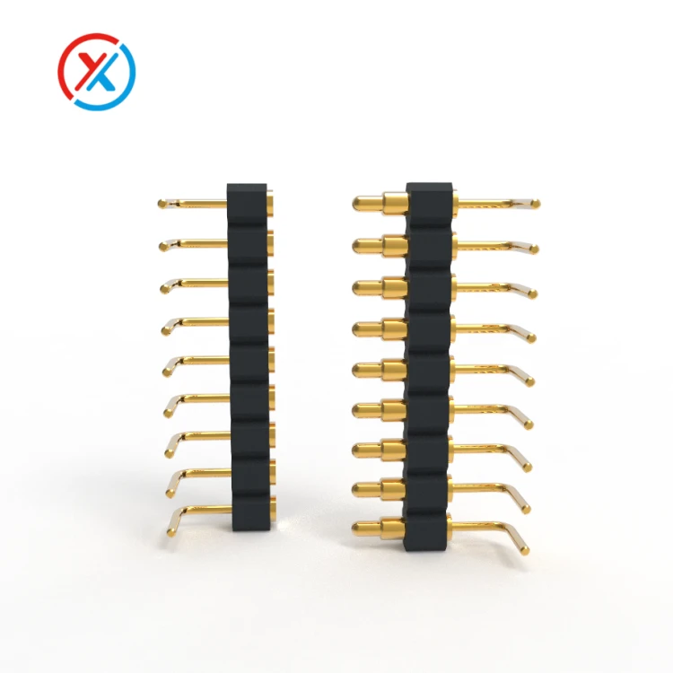
Customization may involve changing contact height, pitch, working travel, spring force, mounting features, or termination style. Precision-machined contacts and supporting parts can help resolve a specific space or alignment constraint without requiring the device to accommodate an unsuitable standard interface.
Material and coating selection should follow the operating conditions. A gold-plated contact system can support stable electrical contact, but performance depends on coating thickness, coverage, adhesion, mating materials, and wear.
Internal movement matters as well. Plunger and barrel dimensions, surface finish, cleanliness, and finished clearance after plating influence compression and return. A contact that sticks after assembly cannot compensate for dimensional variation as intended.
Repeated docking tests should therefore examine more than whether the terminal still charges. Relevant checks include:
Contact resistance, voltage drop, and temperature under load.
Retention and release behavior with the intended handling directions.
Plunger movement, return, and force at working compression.
Contact wear and mating-pad condition after repeated engagement.
Charging and communication stability during specified movement.
Performance after relevant moisture, contamination, and cleaning exposure.
Acceptance criteria should be established before sample approval. The tested configuration should remain linked to its contact design, materials, plating, mating pads, mounting arrangement, and termination process.
For custom development, the most useful starting package includes the terminal and dock drawings, electrical assignments, available space, operating load, and expected handling conditions. These inputs allow the connector design and validation plan to address the actual working environment.
1. Can one pogo pin interface support charging and data transfer?
Yes, when the contacts, wiring, and connected electronics support both functions. Validation should include data communication while the interface carries the intended charging load.
2. Are flush pogo pin interfaces automatically waterproof and dustproof?
No. A flat surface may be easier to inspect and clean, but environmental protection depends on the complete sealing arrangement. Connected and disconnected conditions may have different protection characteristics.
3. Can a pogo pin connector directly replace an existing USB interface?
It requires a design review. Power, signal assignments, charging control, mounting, and device compatibility must be addressed. A contact interface may reproduce selected functions, but matching the required number of conductors alone is insufficient.
4. What can XINTENG customize for a handheld terminal project?
Customization can include contacts, pin arrangements, carriers, housings, mounting parts, magnetic retention, and cable terminations. Device drawings, electrical requirements, environmental exposure, and expected connection cycles provide the basis for development and sample evaluation.


