


Reliability must be evaluated against those demands. The useful questions are whether the connection remains stable during operation, how it changes with wear and environmental exposure, and whether a disconnection affects the device's intended function.
Pogo pins can support compact, detachable interfaces through spring-loaded pressure contact. Their plungers compress against mating pads, providing a defined amount of axial travel to accommodate variation in the assembled position.
They remain direct-contact electrical connectors. A wearable monitor may communicate wirelessly while using pogo pins for charging, but the pins themselves do not transfer power wirelessly.
Contact resistance is one of the main electrical characteristics to control. Excessive resistance can produce voltage drop and heating in a power path. In a signal interface, inconsistent contact can cause interruptions or unstable communication.
A single resistance reading provides limited information. The measurement should identify the contact compression, mating components, measurement points, and test conditions. Subsequent measurements should use comparable conditions so that changes can be assessed meaningfully.
Movement-related testing is equally important where the device or accessory can shift during use. A connection may pass a stationary continuity check yet develop brief interruptions when its mounting structure moves.
The mechanical design should therefore keep each pin within its working range. Guides control alignment, stops prevent overcompression, and retention features maintain engagement. The spring provides axial compliance; it does not compensate for unrestricted lateral movement or inadequate mounting.
Contact force varies with compression. The drawing should specify the required force at the installed working position, together with the permitted travel range. Multi-pin assemblies also need assessment of their combined spring load and the stiffness of the supporting structure.
The expected operating pattern helps determine which reliability tests matter most.
| Operating pattern | Main concern | Evaluation focus |
|---|---|---|
| Frequent docking or accessory replacement | Contact wear, contamination, and changes in engagement | Repeated mating followed by electrical and mechanical checks |
| Long periods of continuous engagement | Force retention, temperature, and sustained compression | Performance during and after the specified operating period |
| Connection during handling or movement | Momentary separation and fretting-related damage | Continuity or communication monitoring under representative movement |
Mating life should be derived from the product's expected use. A device charged several times during a working day has a different connection schedule from an internal module removed only for servicing.
A statement such as "100,000 mating cycles" needs supporting conditions. Stroke, alignment, mating-pad finish, cycling rate, electrical load, environment, and acceptance limits all affect what that figure means.
Mechanical cycling without load does not establish durability during energized connection and disconnection. If the interface makes or breaks a live circuit, the electrical design must address that operating condition.
Cycle count also does not describe every form of aging. A contact that remains compressed may experience changes in spring force or electrical performance over time. Where relevant, sustained-compression testing should complement mating-cycle tests.
Materials and finishes need to suit the actual exposure. Conductive components require appropriate electrical and mechanical properties. Springs need suitable force retention, while carriers and housings must maintain contact positioning and insulation.
Material evaluation should distinguish between internal parts, accessible surfaces, and parts that may contact the patient. Environmental material declarations, chemical compatibility information, and evidence relevant to patient contact serve different purposes.
Gold over a suitable underlayer is one possible contact finish. It can help maintain a stable contact surface, but performance depends on coating thickness, coverage, adhesion, mating materials, and wear.
Gold plating does not eliminate contamination or guarantee a service life. Once a finish is worn or damaged, exposed materials and accumulated debris may affect resistance. Surface inspection should therefore be considered alongside electrical measurements.
Cleaning requirements belong in the development brief. A connector intended for routine surface wiping may have different material and construction requirements from one exposed to a specified disinfection or sterilization process.
The relevant conditions should be defined by the device manufacturer. Evaluation needs to consider contact finishes, plastics, seals, adhesives, cable jackets, and markings together. Changes after repeated exposure may affect both mechanical integrity and electrical performance.
The interface should also be accessible for its intended maintenance procedure. Recesses, moving plungers, and housing joints need assessment for retained moisture or debris. Sealing around the connector body does not automatically establish protection at every exposed contact surface.
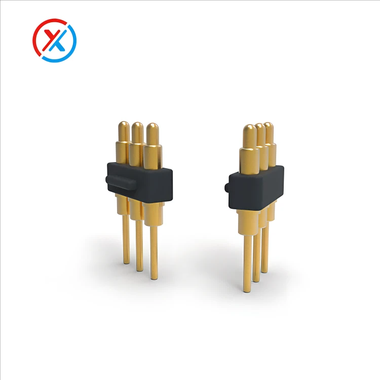
Power testing should include the complete supply and return paths. Contacts, mating pads, solder joints, wiring, and PCB conductors all contribute resistance. Temperature should be assessed in a representative enclosure with the contacts at their intended compression.
If the device operates while charging, the evaluation should include both operating demand and charging demand. Any required communication should also be checked during that combined load condition.
Low contact resistance is only one part of the electrical design. Insulation, contact spacing, polarity, and connection sequencing require their own assessment where applicable. A component rating does not establish the performance of the complete medical device.
Precision manufacturing supports consistency between approved samples and production parts. Plunger and barrel dimensions, surface finish, cleanliness, and clearance after plating affect movement and return. Carrier dimensions and contact height affect engagement with the mating assembly.
XINTENG supports drawing-based customization of pogo pin contacts, insulating carriers, magnetic connector housings, mating components, and cable assemblies. Development can coordinate these parts around the available space, electrical assignments, working travel, retention method, and termination requirements.
For magnetic interfaces, the holding force should be evaluated with the total spring load, cable forces, and intended release direction. The consequences of separation remain a device-level consideration.
Before production approval, the test plan should define measurable acceptance criteria. These may include resistance limits, allowable interruptions, temperature, contact force, return behavior, retention, and permitted wear after the specified exposure.
The evaluated configuration should remain linked to its drawings, materials, plating, mating parts, and assembly process. Changes to those features need review because they may affect the relevance of earlier test results.
1. How many mating cycles should a medical pogo pin connector withstand?
There is no universal requirement. The target should follow the expected connection frequency and service period. A cycle-life claim is meaningful only when its test conditions and acceptance criteria are defined.
2. Does low initial contact resistance prove long-term reliability?
No. Resistance should also be assessed after relevant wear, movement, temperature, and cleaning exposure. Contact force, retention, and plunger movement contribute to reliability alongside the electrical measurements.
3. Are pogo pin charging interfaces a form of wireless charging?
No. Pogo pins transfer power through direct contact with conductive pads. A device can use wireless communication or other wireless functions while still relying on a physical charging interface.
4. What information is needed for a custom medical-product connector?
Provide the device drawings, electrical functions, voltage, current, signal requirements, installed height, and mounting arrangement. Expected connection cycles, cleaning conditions, environmental exposure, and documentation requirements help establish the design and sample-evaluation plan.


