


Their value comes from fitting the connection to the device's operating needs. A handheld instrument may need an accessible charging cradle, while a wearable monitor may require a small interface that accommodates enclosure tolerances. Pogo pins provide one way to address those requirements without relying on repeated insertion into a conventional socket.
A typical pogo pin contains a movable plunger, a barrel, and an internal spring. When the plunger meets its mating pad, it compresses and establishes electrical contact. The spring supplies pressure, while the internal contact arrangement provides the conductive path.
Contact force varies with compression. It must therefore be specified at the installed working height rather than treated as a constant property of the pin.
This working travel helps accommodate dimensional variation between mating assemblies. Within the approved range, the contact can adjust to differences in enclosure position, PCB mounting, or mating-pad height.
The surrounding structure remains important. Guides should position the contacts correctly, supports should carry the device's weight, and stops should prevent excessive compression. These features allow the spring-loaded contacts to perform their electrical function without receiving unintended mechanical loads.
For equipment returned to a dock throughout the day, pressure contact can simplify connection. The user places the device into a defined position, and the contacts engage as the assembly seats. The dock geometry, retention mechanism, and electrical controls determine how consistently that action works.
| Equipment type | Possible pogo pin application | Main integration priorities |
|---|---|---|
| Portable patient monitor | Charging dock or removable module | Repeatable seating, retention, and continuity during the specified movement |
| Handheld diagnostic instrument | Charging and service interface | Contact access, cleaning compatibility, and compact installation |
| Wearable monitoring device | Charging or accessory connection | Low-profile packaging, moisture exposure, and controlled contact pressure |
| Therapy equipment | Removable accessory or control interface | Electrical assignments, retention, and application-specific protection |
Each application needs its own evaluation. An interface used only for charging may have different requirements from one connected to a patient-related circuit or carrying measurement signals.
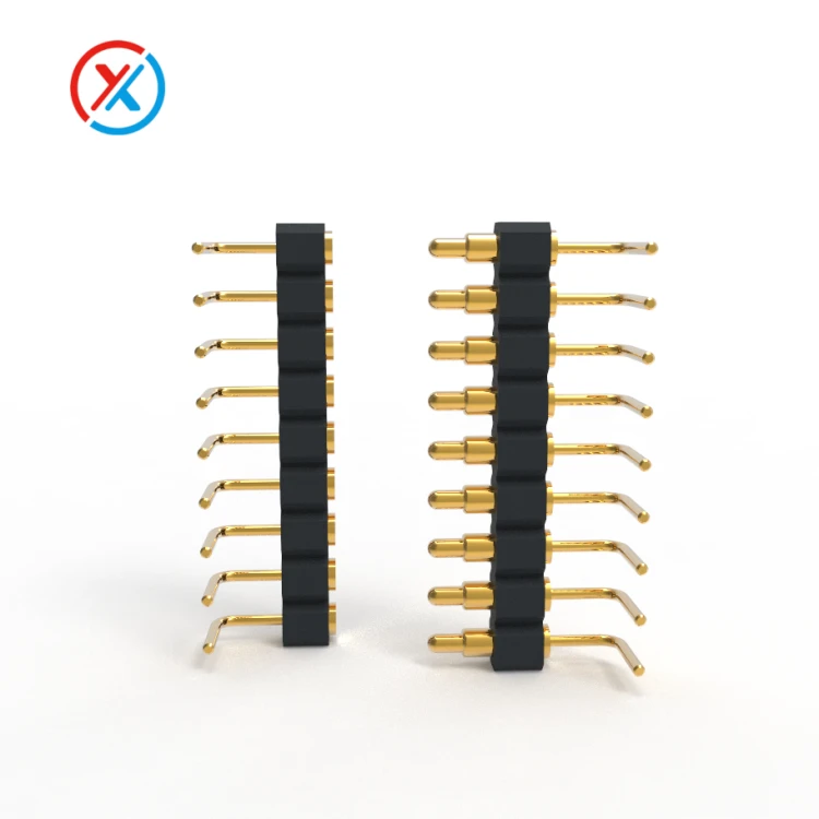
Compact packaging is another practical benefit. Contacts can be arranged in a row or array to suit the available enclosure space. An insulating carrier holds their positions, while the mounting arrangement establishes their relationship to the mating surface.
The complete installation still includes clearance for engagement, structural support, insulation, and any cable routing. Selecting the smallest individual pin does not necessarily produce the smallest workable assembly.
Multiple contacts can combine power, return current, identification, communication, and control functions. Their allocation should follow the electronics design. Pin count alone does not establish the supported data interface or charging capability.
For measurement and communication paths, repeatability matters as much as initial continuity. A connection that performs correctly while stationary may behave differently during handling. Movement-related testing can reveal interruptions or resistance changes that a single resistance measurement would miss.
Power interfaces require assessment of the complete current path. Pogo pins, mating pads, terminations, wires, and PCB conductors all contribute resistance. Voltage drop and temperature should be checked under the intended load and installed compression.
The spring should not be assumed to carry the main current simply because it is inside the contact. The actual conductive path depends on the internal design and needs to be evaluated accordingly.
XINTENG supports custom pogo pin and magnetic connector development from customer drawings. Contact geometry, pin spacing, working travel, insulating carriers, mounting features, and cable terminations can be coordinated around the device and its mating accessory.
For a constrained enclosure, customization may resolve a contact-height or mounting conflict. For a dock, it may involve matching the contact layout to locating surfaces and retention features. Prototype evaluation helps establish whether the proposed geometry works in the assembled equipment.
Material selection connects these mechanical choices with the operating environment. Conductive components need suitable electrical properties, strength, and manufacturability. Springs need to retain the required force, while carriers and housings must maintain contact positioning and insulation.
Material exposure should be identified explicitly. An internal contact, an accessible charging pad, and a skin-contacting housing can require different evaluations. Environmental material declarations do not, by themselves, establish suitability for every medical application.
Surface finishes also need a defined purpose. Gold over a suitable underlayer can help maintain a stable contact surface, but its performance depends on coating thickness, coverage, adhesion, mating materials, and wear.
A plated finish does not eliminate maintenance or contamination concerns. Cleaning agents, moisture, handling residues, and retained debris can affect the interface. The connector should be designed around the device's specified cleaning or reprocessing procedure.
That procedure needs to be known during development. Housing plastics, seals, adhesives, cable jackets, and contact finishes may respond differently to repeated exposure. Evaluation should include the complete assembly and any electrical or mechanical changes after treatment.
Durability has more than one meaning. A charging interface may undergo frequent mating cycles, while an internal module may remain compressed for a long period. Repeated cycling and sustained compression should be assessed separately where both are relevant.
The approved working range should preserve sufficient force at minimum compression and prevent overtravel at maximum compression. In a multi-pin assembly, total spring load and mounting deflection also need consideration.
Magnetic retention can assist attachment, but it is optional. Latches, screws, or cradle geometry may provide the required engagement instead. Where magnets are used, their holding force must be evaluated with the spring load, cable forces, and intended release direction.
Development testing should focus on the conditions that could change the connection's performance:
Alignment and compression across the permitted assembly tolerances.
Resistance, voltage drop, and temperature at the specified load.
Contact stability during relevant movement or vibration.
Wear and force changes after repeated mating.
Force retention during prolonged compression.
Performance after the required environmental and cleaning exposure.
Manufacturing controls should then address the features that produced acceptable samples. Plunger and barrel dimensions, finished clearance after plating, carrier position, contact height, and assembly cleanliness can all influence consistency.
Drawings, material specifications, inspection criteria, and part revisions should remain connected to the approved configuration. Changes need review so that production parts remain representative of the design that was evaluated.
1. Are pogo pin connectors more reliable than conventional connectors?
Reliability depends on the application and the specific designs being compared. Pogo pins offer useful axial compliance and pressure contact, but they still require appropriate alignment, retention, materials, and validation.
2. Can pogo pins remain compressed during continuous equipment operation?
They can when the design is suitable for sustained compression. Evaluation should consider working travel, force retention, temperature, contact resistance, and the required service period.
3. Do medical pogo pin connectors always use magnetic attachment?
No. Magnetic attraction is one retention option. A housing, latch, screw, or dock structure can also maintain engagement. The appropriate arrangement depends on handling requirements and the consequences of separation.
4. What should an OEM provide for a custom medical connector project?
Provide device drawings, available space, contact assignments, voltage, current, signal requirements, and installed height. Include expected handling, connection cycles, cleaning procedures, environmental exposure, and documentation requirements to define sample evaluation.


