


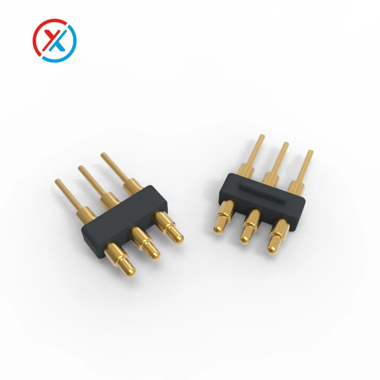
Each contact typically contains a plunger, barrel, and spring. The plunger compresses against a mating pad, while the spring supplies contact force. The internal contact arrangement establishes the conductive path through the component.
For medical equipment, this structure must be developed around the intended use. A charging dock, a removable sensor module, and an interface carrying patient-related signals can have substantially different electrical and mechanical requirements.
The main advantage of a pogo pin is controlled compliance. When the assembled dimensions vary within the specified range, the plunger can move while maintaining contact pressure. This helps accommodate manufacturing tolerances and normal variation in the mating position.
Stable operation still requires appropriate alignment and retention. The housing should guide the contacts onto their mating pads, limit lateral loading, and prevent overcompression. Spring travel alone does not guarantee uninterrupted connection during vibration or impact.
A handheld device returned to a charging cradle illustrates this relationship. The cradle supports and positions the equipment; the contacts compress to their working height; and the retention arrangement keeps the interface seated. Each part contributes to the result.
The contact layout can also support several functions within a compact interface. Separate positions may carry power, return current, communication, identification, or control signals. These assignments need to be defined before selecting the pin count and spacing.
| Development input | What needs to be established |
|---|---|
| Interface function | Charging, signal transfer, accessory detection, or a combination |
| Installed geometry | Contact height, working compression, mating-pad position, and tolerance range |
| Electrical load | Voltage, continuous current, peak-current conditions, and allowable voltage drop |
| Signal requirements | Interface type, grounding, acceptable interruptions, and communication performance |
| Handling conditions | Mating direction, retention, cable loads, vibration, and connection frequency |
| Environmental exposure | Temperature, moisture, cleaning agents, and any required reprocessing |
| Material contact | Whether parts contact the patient, user, internal assembly, or cleaning environment |
| Verification criteria | Electrical, mechanical, environmental, and documentation requirements |
Contact force should be specified at the intended working compression. Too little force may leave insufficient margin for stable engagement. Excessive force can increase wear, make docking difficult, or place unnecessary loads on the enclosure and PCB.
In a multi-pin connector, the total spring force matters as well as the force of each contact. The mounting structure must maintain the required compression across the array without excessive deflection.
Long-term compression and repeated mating also create different demands. A docked accessory may experience many connection cycles, while an internal module may remain compressed for an extended period. The latter requires attention to force retention under sustained compression and operating temperature.
Electrical performance depends on more than the spring. The plunger, barrel, internal contact points, mating pads, and terminations form the conductive path. Their materials and dimensions influence resistance and heating.
For charging applications, evaluation should include both supply and return paths under the intended load. Cable resistance, solder joints, and PCB conductors may contribute as much as the contact interface to voltage drop.
For sensitive signals, the consistency of the connection can be as important as its initial resistance. Intermittent contact during movement may introduce noise or interrupt communication even when a stationary continuity test passes.
Testing should therefore reflect the electrical function. Resistance measurements need defined contact compression and measurement conditions. Movement-related evaluations may require continuity or communication monitoring throughout the test.
Material selection begins with the role of each component. Conductive contact parts need suitable electrical and mechanical properties. Springs need appropriate force, fatigue behavior, and resistance to relaxation. Insulating carriers and housings must maintain their dimensions and electrical separation under the specified conditions.
The exposure of each material also matters. An internal contact, an accessible charging surface, and a skin-contacting enclosure do not necessarily require the same evidence or evaluation. Describing a material as environmentally compliant or "medical grade" does not, by itself, establish suitability for every location in a medical device.
Where an interface forms part of a patient-connected electrical system, insulation and protection requirements need to be defined at the equipment level. A component's material description or contact rating cannot establish the performance of the complete device.
Contact finishes should be selected for the mating conditions and environment. Gold over a suitable underlayer is one possible approach to maintaining a stable contact surface. Its performance depends on thickness, coverage, adhesion, mating materials, and wear.
Gold plating does not independently establish biological compatibility, cleaning resistance, or service life. Those questions require evaluation of the actual finish and assembled product under the intended conditions.
Cleaning and reprocessing requirements should be available early in development. The specified agents, exposure conditions, drying process, and number of repetitions can affect plastics, seals, adhesives, plating, and cable jackets differently.
The connector face should support the intended inspection and cleaning method. Accessible surfaces can make contamination easier to identify, while recesses and moving interfaces need assessment for retained moisture or debris.
Any ingress-protection requirement should identify the relevant assembly condition. Performance while connected may differ from performance while disconnected or covered.
Precision manufacturing supports these requirements by controlling the features that determine movement and engagement. Plunger diameter, barrel bore, straightness, surface finish, and finished clearance after plating can influence internal friction and return behavior.
Carrier dimensions and contact positioning affect engagement across the assembly. A small dimensional change may alter compression or shift a pin toward the edge of its mating pad. These functional dimensions deserve clear drawing requirements and appropriate inspection.
XINTENG supports drawing-based customization of pogo pin contacts, insulating carriers, magnetic connector housings, mating components, and cable assemblies. Development can address the available installation space, contact arrangement, working travel, mounting method, and termination requirements as one coordinated interface.
For magnetic charging designs, retention should be assessed together with spring force, device support, and the intended release action. The design should also consider how separation affects power or communication.
Sample evaluation provides the basis for confirming the proposed configuration. Relevant checks may include:
Mechanical fit, alignment, and working compression.
Contact force and reliable plunger return.
Resistance, voltage drop, and temperature under load.
Signal stability during the specified movement conditions.
Repeated mating and sustained-compression performance.
Electrical and mechanical checks after environmental or cleaning exposure.
The acceptance criteria should be agreed before testing. Samples should represent the intended materials, coating system, mating parts, and assembly method so that the results remain relevant to production.
Approved drawings, material specifications, inspection records, and component revisions should remain linked to the supplied assembly. Changes to materials, plating, dimensions, or processing need review because they may affect previously established performance.
1. Where can pogo pin connectors be used in medical equipment?
They can be considered for charging docks, removable modules, accessory interfaces, and other applications that benefit from spring-loaded contact. Suitability must be established against the particular device's electrical, mechanical, and environmental requirements.
2. Do pogo pins automatically prevent disconnection during vibration?
No. Their spring travel can maintain pressure within a defined range, but performance also depends on alignment, retention, contact force, and mounting stability. Verification should use a representative assembly under the intended movement conditions.
3. Does gold plating make a connector suitable for medical use?
Not by itself. Gold plating can support contact-surface stability, but suitability also depends on material exposure, cleaning conditions, electrical requirements, and the complete device construction.
4. What information is needed for a custom medical-device pogo pin connector?
Provide the drawings, available space, contact assignments, voltage, current, signal requirements, and installed height. Expected connection cycles, retention, cleaning procedures, environmental exposure, and documentation needs help define development and sample approval.


