


Each pogo pin contains a spring-loaded plunger that compresses against a mating pad. Once the assembly reaches its intended position, the contacts establish the electrical paths required for power, communication, or accessory identification.
This arrangement can make frequently used connections easier to access. A tablet can be placed in a charging cradle or attached to a keyboard without inserting a separate cable into a small socket. The finished design still needs controlled alignment, suitable contact pressure, and compatible electronics.
The benefits are most useful when the connector is developed around a specific accessory.
| Application | Interface function | Main design priorities |
|---|---|---|
| Charging dock | Supplies charging power, with detection or identification if required | Repeatable positioning, current capacity, temperature, and tablet support |
| Detachable keyboard | Provides keyboard power and communication | Contact mapping, accessory recognition, retention, and firmware support |
| Expansion dock | Carries supported power, data, or control connections | Signal arrangement, grounding, interface compatibility, and mechanical stability |
| Protective case with electronics | Connects an integrated keyboard or another powered accessory | Case fit, contact alignment, cable routing, and movement during use |
A passive magnetic cover may require no electrical contacts at all. Pogo pins become relevant when the cover contains electronics that need power or communication with the tablet.
For younger users, a well-guided mating action can reduce the precision required to connect an accessory. The housing can direct the tablet toward its seated position, while magnets, latches, or the dock geometry maintain engagement.
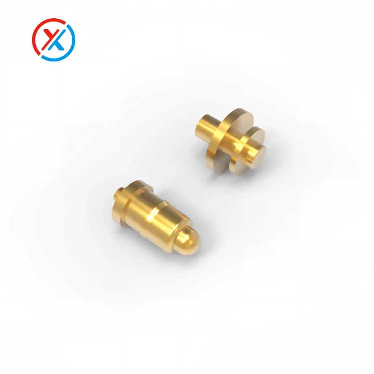
Magnetic attraction is optional. It can assist positioning and attachment, but it should work with locating features that control the final contact position. The pins must land within their mating pads and reach the specified working compression.
The tablet's weight and normal handling loads should be carried by the accessory structure. A charging cradle needs supporting surfaces, while a keyboard attachment may need a hinge or other retention features. The contacts should remain within their permitted mechanical loading.
Pogo pins provide compliance primarily along their compression direction. That helps accommodate a defined variation in mating height, but it does not make the interface tolerant of unrestricted sideways movement.
The mechanical review should include PCB position, contact height, carrier dimensions, enclosure tolerances, and mating-pad location. At minimum compression, every required contact must still engage properly. At maximum compression, the structure should prevent overtravel.
Contact force also influences the user experience. Too much combined spring force can make an accessory difficult to seat or cause a lightly retained connection to separate. Too little force may leave insufficient margin for stable contact.
For magnetic assemblies, retention and release should be evaluated together. Cable pull, accessory weight, and the direction in which a user removes the tablet can change the apparent holding force. Testing only a straight axial pull may not represent normal classroom handling.
Electrical functions need their own specification. A keyboard interface may carry power and control data, while an expansion dock may require a more demanding communication path. The contact count should follow those requirements.
Adding pins does not automatically add charging power or data capability. Contact assignments, wiring, PCB routing, and the tablet's electronics must support each function. Accessory detection and operating-system or firmware support also affect whether the connected keyboard or dock works as intended.
Charging should be assessed through the complete supply and return paths. The pogo pins, mating pads, terminations, PCB conductors, and any cable all contribute resistance. Excessive resistance can cause voltage drop and local heating.
The intended charging current, operating voltage, allowable temperature rise, and installed contact compression should be defined before selecting the contact. If several contacts share a power connection, their current distribution needs evaluation rather than assuming equal sharing.
A classroom charging station introduces additional thermal considerations. Several tablets charging together can create conditions that differ from a single exposed sample. The connector and dock should be evaluated in a representative arrangement with the intended electrical load.
Where charging and communication operate simultaneously, testing should cover that combination. A keyboard or accessory that communicates correctly under a light load still needs verification while the tablet is charging at its specified level.
XINTENG supports drawing-based customization of pogo pin contacts, magnetic connector housings, insulating carriers, mating components, and cable assemblies. For an educational tablet, the interface can be coordinated with the enclosure, PCB layout, keyboard attachment, or charging cradle.
Customization may involve contact height, pitch, spring force, working travel, mounting features, or cable exit direction. Precision machining and assembly control help maintain the dimensions that affect movement and engagement.
Finished dimensions after plating deserve attention. Plunger-to-barrel clearance affects internal movement, while contact height and carrier position affect mating with the accessory. These features should remain linked to the approved drawing and inspection criteria.
Surface finishes contribute to contact stability and wear resistance. Gold over a suitable underlayer is one possible approach, but performance depends on coating quality, thickness, mating materials, contact force, and exposure.
A pressure-contact interface still experiences wear. The external contact surface can move during engagement, and the plunger moves inside the barrel during compression. Durability should therefore be established through testing rather than inferred from the connector's appearance or attachment method.
Classroom exposure can include dust, handling contamination, cleaning products, and occasional moisture. The contact face should be accessible for the intended inspection and cleaning procedure. Recesses and guides should avoid unnecessarily trapping debris around the pins.
Exposed contacts also require consideration of accidental conductive bridging. Contact spacing, housing geometry, and the device's electrical protection should reflect the intended use. If water resistance is required, the specification should identify whether it applies while connected, disconnected, or covered.
A practical sample evaluation should include:
Fit and alignment: confirm engagement across the permitted tablet and accessory tolerances.
Attachment and removal: assess retention, release direction, and normal handling loads.
Electrical performance: measure resistance, voltage drop, and temperature at the intended current.
Accessory operation: verify recognition and communication, including simultaneous charging where required.
Repeated use: check contact wear, spring-force changes, and plunger return after the specified cycles.
Environmental exposure: evaluate relevant cleaning, contamination, moisture, and temperature conditions.
The acceptance criteria should describe both electrical and mechanical performance. An interface that still charges after cycling may nevertheless have excessive resistance, damaged plating, or insufficient retention.
For development, provide the tablet and accessory drawings, available connector space, electrical assignments, charging requirements, and expected handling conditions. These inputs allow sample evaluation to address the actual classroom configuration before the interface is released for production.
1. Can pogo pin connectors support charging and keyboard communication at the same time?
Yes, when the contact arrangement, wiring, and tablet electronics support both functions. Verification should include keyboard operation while the interface carries the intended charging load.
2. Do pogo pin tablet connectors always need magnets?
No. A cradle, latch, hinge, or other mechanical structure can maintain engagement. Magnets are an optional way to assist alignment and retention; they do not replace the need for controlled contact positioning.
3. Are pogo pin connections more durable than USB connections?
Durability depends on the specific designs and operating conditions. A pogo pin interface can reduce repeated use of a separate socket, but its contacts still experience wear. Compare assemblies using relevant mating, handling, electrical, and environmental tests.
4. What can XINTENG customize for an educational tablet project?
Customization can cover the contacts, housing, insulating carrier, magnet arrangement, mounting features, cable assembly, and device-side mating parts. Customer drawings, electrical requirements, and expected use provide the basis for confirming the design and evaluating samples.


