


As wear progresses, it can remove or displace the surface finish, expose underlying materials, and generate debris. The electrical consequences may include rising contact resistance, intermittent signals, voltage drop, or increased heating.
The rate of wear depends on the combination of contact force, sliding distance, geometry, materials, surface condition, and lubrication. A visible wear mark alone does not establish failure. Its significance depends on the remaining coating, the condition of the contact path, and the measured electrical performance.
During normal mating, the contact surfaces slide across one another over a designed distance. This movement helps establish engagement and, in some designs, provides a wiping action that can displace surface films. It also subjects the finish to repeated friction.
The amount of wear depends on how the contacts approach, where they first touch, and how the load develops during engagement. Misalignment can concentrate pressure on an edge or a small portion of the contact surface, producing wear that differs substantially from the intended mating pattern.
Small movements while the connector remains engaged are commonly associated with fretting. Although each displacement is limited, repeated motion can accumulate considerable sliding distance over time.
Fretting can arise from vibration, movement of an unsupported cable, enclosure flexing, or thermal expansion differences between connected parts. Wear particles may remain trapped near the contact rather than being carried away during a full mating stroke.
Where exposed materials or debris oxidize, resistive products can accumulate at the interface. This interaction between movement, wear, and surface reaction is often described as fretting corrosion. A connector can therefore develop unstable resistance even when it has undergone relatively few complete mating cycles.
Several wear mechanisms can act on the same contact:
| Mechanism | What happens at the interface | Possible evidence |
|---|---|---|
| Adhesive wear | Small metallic junctions form and separate during sliding, transferring or removing material | Material transfer, roughened tracks, and particles |
| Abrasive wear | Hard surface features or trapped particles cut or plough the contacting surfaces | Scratches, grooves, and localized coating loss |
| Fretting-related damage | Repeated small movements produce local wear, retained debris, and sometimes corrosion products | Concentrated wear patches and unstable contact resistance |
Adhesive wear begins at microscopic surface irregularities. Even a polished contact touches its mating surface through local regions rather than across its entire apparent area.
Under pressure, some of these regions deform and form metallic junctions. As the surfaces move, the junctions separate. Separation can occur within one of the contacting materials, leaving transferred metal or detached particles.
This microscopic bonding is sometimes described as cold welding. Its occurrence and severity depend on the materials, films, loading, surface condition, and lubrication. There is no universal contact-force threshold at which every connector changes from mild wear to severe adhesive wear.
Detached particles can introduce another mechanism. If they are sufficiently hard and become trapped between the contacts, they can act as abrasives. External dust or manufacturing debris can produce similar damage.
A simplified way to describe sliding wear is the Archard relationship:
V = k × F × L / H
Where:
V is the volume of material removed.
k is an empirical wear coefficient for the particular contact conditions.
F is the normal load.
L is the accumulated sliding distance.
H is the hardness of the material being worn, commonly associated with the softer material in a simplified treatment.
The relationship helps explain why load, movement, and material hardness matter. It is not a direct calculator for connector service life.
The wear coefficient can change substantially when the mechanism, lubrication, contamination, or surface condition changes. Coated contacts also behave as layered systems: the top finish, underlayer, and substrate all influence deformation and wear.
Accumulated sliding distance includes repeated movement in both directions. A contact that returns to its starting position after each vibration cycle can still accumulate wear.
For approximately uniform material removal over a defined wear area, average thickness loss can be estimated from t = V / A. Actual connector tracks are often uneven, however. Local coating breakthrough may occur before the average thickness loss appears significant.
Contact force must be selected together with these effects. Adequate force helps establish electrical contact and resist disturbances. Excessive force can increase local stress, friction, and mechanical loading.
Reducing force without checking electrical performance can create a different problem: insufficient contact stability or unreliable engagement. The useful target is a force range that satisfies electrical and mechanical requirements throughout the working travel.
Some connector designs use several contact beams or contact points to distribute load and provide parallel electrical paths. Their effectiveness depends on geometry, manufacturing consistency, and actual engagement. Neither force nor current should be assumed to divide equally without evaluation.
Surface finish and coating quality also affect wear. Hard gold can offer useful wear resistance for repeated contact applications, but its performance depends on deposit properties, thickness, underlayer support, mating materials, and operating conditions.
Tin and gold finishes should not be ranked using hardness alone. Their surface films, contact-force requirements, friction, and wear mechanisms differ. The appropriate comparison is between complete contact systems tested under relevant conditions.
A thicker finish can provide additional material before an underlying layer becomes exposed. It cannot compensate for severe misalignment, abrasive contamination, poor adhesion, or an unsuitable contact geometry.
The nickel underlayer in a gold-plated contact forms part of the mechanical and corrosion-protection system. Its condition and thickness can influence how the top layer is supported. Poor surface preparation or coating adhesion may also cause flaking, which requires investigation beyond normal sliding wear.
For pogo pins, wear can occur at both the external mating surface and the internal plunger-to-barrel interface. The plunger moves within the barrel during compression, and the internal contact structure may apply lateral force to maintain conduction.
Bore finish, plunger dimensions, straightness, clearance, coating distribution, and cleanliness all affect that movement. Roughness, burrs, deformation, or trapped particles can produce localized wear and inconsistent return.
Finished dimensions after plating are particularly important. A fit that is suitable before coating may become too tight afterward. Conversely, excessive clearance can permit movement that the contact design was not intended to accommodate.
External alignment remains equally important. Guide features should bring the mating pad into position before substantial compression occurs. Mechanical stops should prevent overtravel, while the enclosure or mounting structure should carry lateral loads.
Lubrication can reduce friction and adhesive interaction in a suitable contact system. Its selection requires attention to electrical behavior, plastics, seals, temperature, migration, contamination, and cleaning.
An appropriate contact lubricant must be applied in a controlled amount and validated for the intended use. General-purpose grease should not be assumed suitable for precision electrical contacts. Lubrication also cannot correct a damaged barrel, poor alignment, or an uncontrolled dimensional fit.
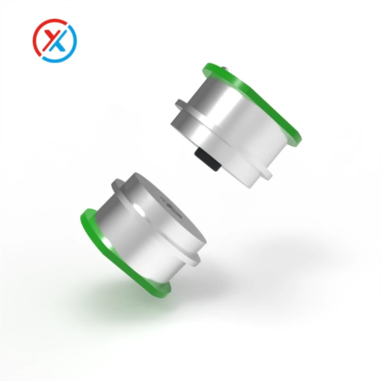
At XINTENG, drawing-based customization can address wear through changes to plunger geometry, barrel dimensions, contact travel, spring force, insulating carriers, and mating features. Reviewing these parts together helps identify whether the problem originates at the external interface, inside the pin, or in the device mounting.
A wear investigation should begin by recording where the damage occurs and under what conditions. Compare samples before and after testing, preserve debris where practical for analysis, and relate the wear pattern to the actual direction of motion.
Useful evaluation includes contact resistance, force versus travel, plunger return, dimensional checks, and surface inspection. Depending on the suspected failure, further examination may be needed to distinguish coating wear-through, material transfer, corrosion, or adhesion failure.
Durability testing should define the mating stroke, alignment, electrical load, cycling conditions, and maintenance procedure. Where vibration or temperature changes are relevant, the validation should include those conditions rather than relying only on repeated insertion tests.
Acceptance criteria should combine surface condition with function. Coating coverage, resistance, retention, contact force, and movement need limits appropriate to the product. Any design change should then be assessed under comparable conditions so that its effect can be distinguished from changes in the test itself.
1. Does a visible wear track mean a connector has failed?
No. A track can develop during normal use. Assessment should consider remaining coating, exposed materials, debris, contact resistance, and mechanical performance against the specified acceptance criteria.
2. Will thicker gold plating always increase connector life?
Additional thickness may delay coating breakthrough, but the result depends on the wear mechanism and coating quality. Misalignment, rough internal surfaces, contamination, or poor adhesion can still cause early failure.
3. Can lubrication solve a connector wear problem?
A suitable contact lubricant can reduce friction and wear in a compatible design. It must be evaluated for electrical performance, material compatibility, migration, and environmental exposure. Mechanical defects require separate correction.
4. Why can a connector wear even when it is rarely unplugged?
Vibration, cable movement, and thermal expansion can create repeated small movements between engaged contacts. This fretting can generate debris and corrosion products, causing resistance instability without frequent full mating cycles.


