

Many connectors provide a separable interface, allowing equipment to be assembled, tested, maintained, or replaced without repeatedly cutting and reconnecting wires. The connection must remain electrically stable and mechanically secure under its intended operating conditions.
The term also includes optical connectors. These align optical fibers so that light can pass between them. Their function is to establish an optical signal path, while electrical connectors use conductive contacts to carry current.
A connector's construction follows the job it needs to perform. A compact sensor interface, a battery connection, and a high-speed data connector may differ substantially in contact geometry, insulation, retention, and mounting.
Most electrical connector assemblies contain several functional elements:
| Component | Main function | Design considerations |
|---|---|---|
| Electrical contacts | Carry power or signals across the interface | Material, surface finish, geometry, contact force, and resistance |
| Insulating carrier | Positions and electrically separates contacts | Spacing, dimensional stability, insulation properties, and temperature |
| Housing | Supports and protects the assembly | Installation space, alignment, handling, and environmental exposure |
| Retention features | Maintain the intended engagement | Latches, screws, friction, magnetic attraction, or other mechanisms |
| Terminations | Join contacts to wires, cables, or PCBs | Soldering, crimping, press-fit, screw connection, or another specified method |
These elements may be combined in different ways. A single spring-loaded contact can form part of a connector without having a separate outer housing. A larger cable connector may contain multiple contacts, an insulating insert, a shield, a locking mechanism, and strain relief.
The mating interface and the termination are also different parts of the assembly. A connector may unplug from its mating half while remaining permanently soldered to a PCB or crimped to a wire.
Connectors simplify production by allowing parts of a product to be assembled and inspected separately. A cable harness, sensor module, display, and main PCB can each be prepared before final integration. Their interfaces then provide defined connection points during assembly.
This benefit depends on the design being practical to install. Orientation features, accessible mounting points, clear contact assignments, and suitable tool clearance help operators make the intended connection consistently.
Serviceability is another reason to use connectors. A replaceable module can be disconnected and removed without disturbing unrelated wiring. For equipment that needs regular maintenance, access to the connector and its release mechanism should be considered alongside its electrical specification.
Connectors can also support product upgrades. A device may accept a replacement module through an established interface, provided the mechanical arrangement, electrical assignments, and operating requirements remain compatible. Matching the connector shape alone does not establish that compatibility.
Design flexibility comes from choosing where the interfaces sit within the product. Engineers can divide a system into assemblies that suit manufacturing, testing, transport, and maintenance. A custom connector may be useful when an existing interface conflicts with the enclosure or PCB layout.
Several connection arrangements appear frequently in electronic equipment:
Board-to-board connections: link PCBs within an assembly, with spacing and alignment controlled by the product structure.
Wire-to-board connections: join a cable or individual wires to a PCB.
Wire-to-wire connections: provide a separable junction between cable sections or harnesses.
Device-to-dock connections: establish power or communication when a product is placed in a cradle or mating fixture.
Panel interfaces: provide an accessible connection through an equipment enclosure.
These descriptions identify where a connector is used. Other terms describe its technology or mounting method. A connector can, for example, use spring-loaded contacts, attach to a PCB by surface-mount soldering, and serve a device-to-dock interface at the same time.
Pogo pin connectors use a movable plunger supported by an internal spring. When the mating parts meet, the plunger compresses against a conductive pad or contact. The spring maintains pressure within the specified working range.
This arrangement is useful for charging docks, test fixtures, removable modules, and other interfaces that benefit from axial compliance. The working travel can accommodate a defined variation in mating height, provided the surrounding structure controls alignment and prevents excessive compression.
In a multi-pin assembly, an insulating carrier holds the contacts at the required spacing. Contact height, carrier position, mating-pad dimensions, and mounting tolerances all contribute to reliable engagement.
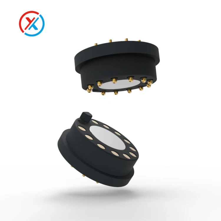
Magnetic connectors add magnetic alignment and retention to an electrical interface. In a magnetic pogo pin assembly, the magnets help position and hold the mating parts, while the metal contacts carry power or signals.
The magnetic force must work with the combined spring force, cable loading, and intended release action. Guide features and stops remain important because magnetic attraction alone does not establish correct contact compression or polarity.
Electrical requirements should be defined before selecting a connector. The main specifications include:
Operating voltage and insulation: identify the voltage between contacts and the required electrical separation.
Continuous and peak current: specify the load and the conditions under which it must be carried.
Contact resistance: establish acceptable resistance and measurement conditions.
Signal requirements: define the communication interface, grounding, and any necessary signal-performance evaluation.
Mechanical requirements: specify mating direction, retention, working travel, and expected connection cycles.
Environmental exposure: identify temperature, moisture, contamination, vibration, and cleaning conditions.
Current capacity depends on the complete conductive path. Contacts, mating surfaces, wires, terminations, and PCB connections can each contribute resistance and heating. The rating should therefore be assessed in the intended installation.
For data interfaces, stable DC continuity is only part of the requirement. Contact arrangement, return paths, cable construction, and PCB transitions influence signal behavior. A connector that carries charging power successfully still needs appropriate evaluation before data capability is claimed.
Materials and finishes should suit the application. Conductive contact materials need to balance electrical performance, strength, wear, and manufacturability. Plating can help control contact-surface behavior, but its suitability depends on the coating system, mating materials, and expected use.
The housing and insulating carrier also require attention. Their dimensional stability affects contact positioning, while their mechanical and environmental properties influence how the assembly performs during installation and service.
At XINTENG, customer drawings can guide the development of custom pogo pin contacts, magnetic connector assemblies, insulating carriers, mounting parts, and cable terminations. This allows the interface to be coordinated with the available space and the device-side mating components.
Customization may involve changing contact height, pitch, housing shape, mounting features, cable exit direction, or termination method. The scope should follow the integration problem. An established connector remains a practical choice when it already meets the requirements.
Prototype evaluation should check the connector in a representative assembly. Fit, alignment, retention, electrical performance, and the required durability or environmental conditions should be assessed against agreed acceptance criteria.
The approved drawing and inspection requirements then provide the production reference. Critical dimensions, material and plating specifications, contact assignments, and test conditions should remain linked to the supplied part revision.
1. What is the main function of an electrical connector?
It establishes an electrical path between components, cables, boards, or devices. Many connectors also allow that path to be separated for assembly, maintenance, or replacement.
2. How does a pogo pin connector differ from a conventional plug-and-socket connector?
A pogo pin uses spring-loaded pressure contact against a mating surface. Its working travel provides axial compliance. A conventional plug-and-socket connector uses an inserted mating arrangement, with contact behavior determined by its particular design.
3. Are connectors with the same pin count interchangeable?
No. Contact spacing, housing geometry, polarity, signal assignments, electrical ratings, and retention features must all match. Pin count describes the number of contact positions, not compatibility.
4. What information is needed for a custom connector?
Provide the mechanical drawings, installation space, mating direction, contact assignments, voltage, current, and signal requirements. Mounting method, expected connection cycles, environmental exposure, and cable details help define the design and sample evaluation.


