


Each connection has a different purpose. An internal board connection, an external charging contact, and a patient-connected accessory should have their own mechanical, electrical, and environmental requirements.
For equipment manufacturers, the design task begins with identifying what the interface must carry, how people will use it, and what happens if the connection becomes intermittent or separates.
A small connector can save enclosure space, but its complete installation includes mounting features, cable bend clearance, strain relief, sealing, and access for assembly. These features influence the practical size of the interface as much as the contact dimensions.
On a wearable product, connector position also affects comfort. A protruding housing or stiff cable exit may press against the body or pull on the device during movement. The mechanical layout should therefore be reviewed with the intended wearing position and cable routing.
For a handheld instrument, the priorities may include grip, orientation, and convenient access. A charging dock introduces another set of requirements: repeatable positioning, support for the device, and contact engagement across the expected assembly tolerances.
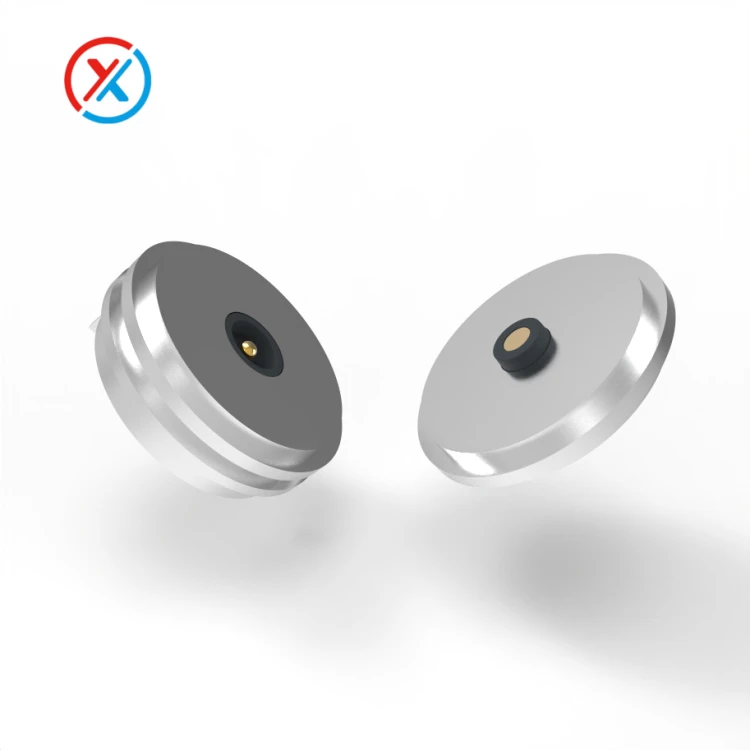
Pogo pin connectors can be considered where an interface benefits from axial compliance and repeated pressure contact. Their spring-loaded plungers compress against mating pads, allowing the connection to accommodate a specified variation in mating height.
That compliance has limits. The surrounding structure should control lateral movement and prevent excessive compression. A dock should support the device through its housing and locating surfaces, with the contacts operating within their designed travel.
Magnetic attachment can assist docking and simplify connection, particularly for small devices. The magnets must hold the interface seated against the combined spring force and any compressed seals. Cable weight, pull direction, and normal handling also affect retention.
The required release behavior should be defined explicitly. A connection designed to separate under a pull may limit the force transferred to the device, but separation can also interrupt power or monitoring. The appropriate balance belongs in the device's risk assessment and operating requirements.
Electrical performance needs equally specific definitions. A connector carrying charging power is evaluated differently from one carrying a low-level sensor signal or a high-speed data interface.
For power connections, the assessment includes the complete supply and return paths: contacts, mating pads, terminations, wiring, and PCB connections. Resistance contributes to voltage drop and heating, so current testing should use the intended contact compression and a representative installation.
For low-level signals, contact stability, contamination, cable movement, shielding, and grounding can affect measurement quality. A connector that passes a basic continuity test may still introduce intermittent behavior during movement.
Digital communication adds requirements for contact assignments, return paths, and the transitions between cable, connector, and PCB. Data capability should be verified for the intended interface and cable length rather than inferred from the number of contacts.
Combining power and communication in one connector can reduce the number of external interfaces. It also requires careful allocation of contacts, insulation spacing, grounding, and mechanical orientation. Different electrical functions may need different contact sizes or construction within the same housing.
Material selection should follow these functions and the operating environment. Copper alloys are possible choices for conductive contact components, while spring materials must provide the required force and retain it through the specified service conditions.
Gold plating can help maintain a stable contact surface, but its suitability depends on the complete coating system, mating materials, contact force, and expected wear. Thickness, adhesion, coverage, and surface preparation all matter. A gold-colored appearance does not establish durability.
The soldering or crimping region may require a different finish from the exposed mating surface. Treating these areas separately allows the termination process and contact performance to be evaluated on their own requirements.
Housing and strain-relief materials need assessment for mechanical strength, temperature, moisture, and chemical exposure. Describing a plastic as "medical grade" does not specify how the finished connector will perform under the product's actual cleaning and handling conditions.
Cleaning, disinfection, and sterilization should be defined separately in the development brief. A connector intended for surface wiping may have very different requirements from an assembly subjected to repeated sterilization.
The relevant inputs include the cleaning agent or process, concentration where applicable, exposure duration, temperature, drying conditions, and number of cycles. Validation should examine the assembled connector, including plastics, plating, seals, adhesives, cable jackets, and markings.
Changes may appear gradually. A housing can lose strength, a seal can change dimensions, or a cable jacket can stiffen after repeated exposure. Electrical and mechanical checks after the specified treatment are therefore more informative than an initial material compatibility statement alone.
The contact face should also support the intended maintenance procedure. Accessible surfaces make inspection and cleaning easier. Recesses may protect contacts from handling, but their geometry should avoid unnecessary debris or moisture retention.
Environmental protection depends on the complete assembly. Housing joints, cable entries, mounting interfaces, and moving contacts can each affect ingress resistance. The required protection should be specified for the connected, disconnected, or covered condition, as appropriate.
A sealed enclosure does not automatically establish the protection of an exposed connector face. Similarly, resistance to water ingress does not establish compatibility with a particular disinfectant or sterilization process.
Mechanical retention deserves its own acceptance criteria. Insertion force, release force, cable pull resistance, and contact compression describe different behaviors and should not be combined into a single "connection strength" value.
The connector should remain secure during intended use while allowing the specified removal action. Keying and housing geometry can help prevent incorrect mating. Color and markings can support recognition, but the mechanical and electrical design should address incompatible connections where required.
Strain relief should transfer cable loads into the supporting structure without concentrating repeated bending at the termination. Its length, flexibility, and exit direction should match the expected handling rather than simply follow the appearance of an existing cable.
Three development approaches are available, depending on how closely an established connector fits the product.
| Development approach | When it is useful | Engineering work to confirm |
|---|---|---|
| Standard connector | Existing dimensions, electrical characteristics, and mounting meet the requirements | Installation, handling, environmental suitability, and device-level performance |
| Modified assembly | An established contact system fits, but the housing, cable, mounting, or strain relief needs adaptation | Effects of the modifications and compatibility with the original contact system |
| Fully custom connector | The product needs a different contact arrangement, envelope, mating geometry, or integrated interface | Part design, tooling, assembly process, inspection, and qualification of the new configuration |
Customization is most useful when it resolves a defined integration problem. Examples include fitting a charging interface into a narrow enclosure, changing the cable exit to improve comfort, or arranging power and signal contacts around an existing PCB layout.
For pogo pin and magnetic connector projects, XINTENG can work from customer drawings to develop precision contacts, insulating carriers, housings, mating components, and cable terminations. Reviewing these parts as a complete interface helps identify fit and assembly issues before production drawings are finalized.
Critical manufacturing features may include plunger and barrel dimensions, finished clearance after plating, contact height, carrier position, and magnet seating depth. The inspection plan should concentrate on the features that control engagement, movement, and electrical performance.
Prototype evaluation should use representative device assemblies. A useful plan may include:
Dimensional and fit checks: confirm mounting, alignment, working travel, and cable clearance.
Electrical measurements: assess resistance, insulation, voltage drop, and any required signal performance under defined conditions.
Mechanical testing: check retention, cable pull, bending, and repeated mating.
Environmental evaluation: apply the specified temperature, moisture, cleaning, or reprocessing conditions.
Post-test inspection: examine contact wear, housing condition, seal integrity, and electrical performance.
Test sequence can matter. Cycling a connector after chemical exposure may reveal a different result from testing untreated samples. The validation plan should reflect the combinations of conditions the product is expected to encounter.
Documentation should identify what each record actually demonstrates. A material declaration, quality-system certificate, supplier registration, and component test report serve different purposes. They should not be presented as interchangeable evidence that the finished medical device is suitable for its intended use.
For custom parts, drawing revisions, material specifications, plating requirements, supplier records, and inspection results should remain traceable to the supplied assembly. Material or process changes need review because they may affect fit, contact behavior, cleaning compatibility, or previously completed testing.
An effective development brief includes the interface drawings, electrical functions, expected handling, required retention, cleaning procedures, service life, and documentation requirements. These inputs give the connector supplier and device manufacturer a shared basis for sample approval and production control.
1. Are pogo pin connectors suitable for portable medical devices?
They can be considered for charging docks, removable modules, and other interfaces requiring spring-loaded contact. Suitability depends on the application's electrical, mechanical, environmental, and reliability requirements. A component's general-purpose rating does not establish suitability for every medical use.
2. Can magnetic connectors provide secure connections for wearable equipment?
They can be designed for defined attachment and release behavior. Validation should include contact force, cable loading, movement, and the consequences of disconnection. Some applications require additional mechanical retention.
3. Can one connector material withstand every cleaning or sterilization process?
No universal compatibility should be assumed. The complete assembly must be assessed against the specified process and number of exposures. Housing materials, seals, plating, adhesives, and cable insulation may respond differently.
4. What information is needed for a custom medical-device connector project?
Provide the mechanical drawings, electrical requirements, mounting arrangement, cable routing, and expected connection cycles. Include the intended cleaning or sterilization process, environmental conditions, retention requirements, and required documentation so that design and validation responsibilities can be agreed early.


