


The interface combines magnets, pogo pins, and mating contact pads. Magnets assist alignment and retention. The spring-loaded pins compress against the pads to complete the electrical circuit. Reliable charging depends on these components reaching the correct position and maintaining suitable contact pressure.
For an OEM project, the connector must fit the eyewear's enclosure, charging electronics, and handling requirements. A compact interface on an AR glasses temple presents different design constraints from a charging dock supporting a larger VR headset.
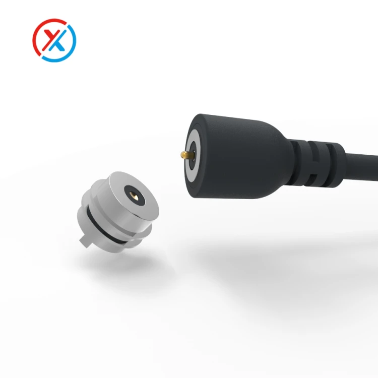
A detachable magnetic cable suits devices that need a compact charging connection without a dedicated cradle. Its connector head, cable exit direction, and strain relief can be developed around the available space.
Cable routing deserves attention early in the design. On glasses, the cable should clear the hinge and avoid interfering with folding. On a headset, it should work with the straps, adjustment mechanisms, and normal handling of the device. Cable weight and pull direction also affect how securely the magnetic interface remains seated.
A charging dock combines the electrical interface with a supporting structure. The cradle guides the headset or glasses into position, supports the device, and establishes the final contact compression. The pogo pins should remain within their permitted mechanical loading rather than carrying the device's weight.
Locating surfaces and stops help make docking repeatable. The design should accommodate normal placement variation without allowing the plungers to strike the edge of a mating pad or receive excessive sideways force.
The contact layout follows the electrical requirements. Pin count alone does not establish charging power, communication capability, or compatibility with a charging protocol.
| Interface requirement | Possible contact arrangement | Design considerations |
|---|---|---|
| Power-only charging | Two contacts for supply and return | Charging control and protection must be provided by the associated electronics |
| Charging with device detection | Three or more contacts | Additional positions can support identification or detection, according to the circuit design |
| Charging with data communication | Multiple contacts allocated to the chosen interface | Signal assignments, grounding, wiring, and PCB transitions require review |
| Power shared across several contacts | Multiple supply and return contacts | Current distribution and temperature must be evaluated for the complete arrangement |
A two-contact interface can provide a power path, but it does not perform charging negotiation or battery management by itself. Where the product requires those functions, the cable, power source, and device electronics must handle them appropriately.
Additional contacts may support device identification, dock detection, temperature-related signals, or communication. Each function needs a defined electrical assignment. Similar-looking connectors should not be treated as interchangeable without confirming their polarity, contact mapping, and operating behavior.
Mechanical design becomes particularly important as the connector gets smaller. The assembly drawing should distinguish free contact height, installed height, recommended working compression, and maximum mechanical travel.
The tolerance assessment needs to include the contact, carrier, enclosure, mating pad, and mounting position. At the smallest expected compression, every required pin should still establish adequate contact force. At the largest compression, the structure should prevent overtravel.
Spring force also affects docking behavior. The magnets must hold the interface seated against the combined force of the contacts and any compressed seals. Increasing magnetic attraction can make removal less comfortable or transfer greater loads into a thin housing, so attachment and release should be evaluated together.
Orientation control should be designed into the mating interface. Housing features, contact placement, and magnet polarity can help guide correct engagement. The electrical design should also address incorrect or partial contact where the geometry allows it.
XINTENG supports drawing-based development of pogo pin contacts, magnetic connector housings, insulating carriers, and cable assemblies. For VR and AR products, these parts can be coordinated with the device-side mating interface so that contact height, magnet position, mounting features, and cable routing are developed together.
Precision machining and assembly control are relevant to this work. Plunger and barrel dimensions influence movement, while the finished dimensions after plating affect clearance. Carrier dimensions and magnet seating depth influence the assembled contact position. These features should be tied to the approved drawing and inspection requirements.
Electrical performance must be checked at the intended working compression. Contact resistance, cable resistance, and termination quality contribute to voltage drop and heating. Both the supply and return paths belong in that assessment.
Thermal evaluation should use a representative enclosure or dock. A contact that performs acceptably in open air may behave differently when surrounded by plastic, adjacent components, or a compact cable overmold.
If the device operates while charging, the power budget must include both operating demand and battery charging. The charging electronics, available source power, heat dissipation, and cable handling all need to support that use. The presence of a magnetic interface alone does not establish suitability for charging during wear.
Sweat and cleaning exposure require particular attention because eyewear is handled frequently and may sit close to the skin. Contact materials, plating, housing materials, seals, and adhesives should be selected for the expected conditions.
Gold over a nickel underlayer is one possible contact finish, but the coating specification should reflect the mating surface, contact force, wear, and exposure. A gold-colored surface does not establish coating thickness or durability.
The connector face should also remain accessible for the intended cleaning method. Deep recesses may shield contacts from some handling but can retain moisture or debris. Exposed magnets can attract ferrous particles, so contact spacing, geometry, and electrical protection should account for that possibility.
Any water-resistance requirement should identify the assembly and its condition during testing. A docked interface, an exposed charging port, and a connector fitted with a cover may have different protection characteristics.
Prototype evaluation should reproduce how the product will be used. Useful checks include:
Docking and alignment: confirm correct engagement across the permitted placement and assembly tolerances.
Attachment and release: measure retention with the actual cable routing or cradle arrangement.
Charging performance: check resistance, voltage drop, and temperature at the specified electrical load.
Repeated connection: inspect wear, contact-force changes, and plunger return after the required cycles.
Environmental exposure: evaluate the relevant sweat, moisture, cleaning, and temperature conditions.
Combined functions: verify data or identification signals while charging, where applicable.
Acceptance criteria should be established before these tests begin. Charging successfully once does not demonstrate that the interface will maintain its performance after repeated docking or environmental exposure.
A useful development brief includes the device drawings, connector location, available space, mating direction, voltage, continuous current, and required electrical functions. Expected connection frequency, cleaning methods, environmental exposure, and whether the device will operate during charging help define the sample evaluation.
1. How many pogo pins are needed for a VR or AR charging connector?
Two contacts can provide a basic supply and return path. Additional contacts may be needed for identification, detection, communication, or current sharing. The circuit requirements and charging architecture should determine the contact count.
2. Can VR headsets or AR glasses be used while charging through a magnetic connector?
They can when the complete device is designed and validated for that operating mode. Source power, charging control, temperature, cable routing, and retention must all be considered. Magnetic attachment alone does not establish suitability for charging during wear.
3. Are magnetic pogo pin connectors resistant to sweat and water?
They can be developed for specified exposure conditions, but performance depends on the complete construction. Contact finishes, seals, housing joints, and cable entries all matter. Testing should distinguish between connected, disconnected, and covered conditions.
4. Can XINTENG customize a charging connector for a narrow glasses temple or compact headset enclosure?
Yes. Customer drawings can guide the contact arrangement, housing dimensions, mounting features, magnet placement, and cable exit. Electrical requirements and operating conditions provide the basis for checking whether the proposed design fits the available space and performs as required.


