


The requirements vary considerably between applications. A charging dock operates under different conditions from a battery connector that supplies power throughout a flight. Selecting the connector starts with understanding that distinction, then defining the current, mechanical loads, environmental exposure, and expected service life.
"High current" describes an application requirement. It does not establish a universal rating for a particular pin size or connector structure.
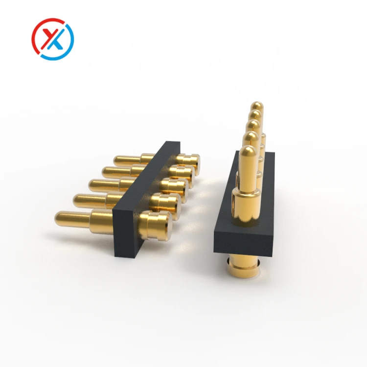
A typical pogo pin contains a movable plunger, a barrel, and an internal spring. The spring provides contact force, while the internal contact arrangement determines how current passes through the assembly. For higher-current designs, the conductive path needs particular attention: material conductivity, component dimensions, internal contact pressure, surface finish, and termination resistance all influence performance.
The entire circuit matters, including the mating pads, supply and return contacts, cables, solder joints, and PCB connections. A rating assigned to an individual contact cannot automatically be applied to the finished drone connector.
| Drone application | Connection function | Main design priorities |
|---|---|---|
| Automated charging dock | Charging power and connection detection | Landing alignment, contact compression, contamination control, and charging sequence |
| Removable battery module | Battery power, identification, and monitoring | Continuous and peak current, positive retention, voltage drop, and connection sequencing |
| Detachable payload | Power and control for cameras, sensors, or other equipment | Available space, mass, mounting stability, and signal requirements |
| Production or maintenance fixture | Temporary power and electrical testing | Repeatable engagement, replaceable contacts, inspection access, and cycle life |
For an automated dock, guide surfaces should bring the drone into its final position before the contacts receive significant compression. The structure should support the aircraft's weight and limit lateral movement. The plungers provide electrical contact and axial compliance; their permitted loading should remain within the contact design.
A removable battery interface requires a separate mechanical review. The latch, battery enclosure, and mounting structure must maintain engagement during the intended vibration and shock conditions. Spring pressure alone does not establish secure battery retention.
The electrical specification should distinguish continuous current from short-duration peaks. Peak magnitude, duration, repetition rate, and recovery time all affect heating. Charging current should also be specified separately from discharge current because the two operating conditions may differ substantially.
Contact resistance becomes especially important as current increases. Resistive heating follows P = I²R, while voltage drop follows V = IR.
For an illustrative contact path with a resistance of 5 mΩ, a current of 20 A produces a voltage drop of 0.1 V and dissipates 2 W. If the supply and return paths each have that resistance, their combined dissipation is 4 W. These are calculation examples, not ratings for a particular pogo pin.
Whether that heat is acceptable depends on the enclosure, conductor dimensions, ambient temperature, nearby components, and available heat paths. Testing should therefore use the intended installation, including its housing, cable routing, and loaded neighboring contacts.
Reducing resistance can improve electrical efficiency, but there is no fixed conversion from a milliohm reduction to a percentage increase in flight time. The result depends on the complete aircraft power budget and operating cycle.
Drawing-based customization helps address these relationships early. XINTENG supports custom pogo pin and magnetic connector assemblies developed around customer drawings, including contact geometry, insulating carriers, mounting features, mating components, and cable terminations. For a drone project, these parts can be reviewed together so that the electrical interface fits the battery enclosure or docking structure.
The machining requirements should follow the features that control performance. Barrel bore size, plunger diameter, straightness, surface finish, and finished clearance affect movement and internal contact behavior. Plating thickness must be included in the dimensional allowance because it changes the fit between mating components.
Material selection also requires a balance. A conductive copper alloy may suit the plunger or barrel, while the spring requires suitable strength, force retention, and fatigue performance. An alloy name alone does not establish the finished connector's current capacity or durability.
Gold over a nickel underlayer is one possible contact finish. Gold can help maintain a stable contact surface, while the underlayer forms part of the coating system. The specified thickness and deposit characteristics should reflect contact force, wear, environmental exposure, and the mating surface.
A thicker coating does not independently solve overheating or guarantee a particular mating life. Coverage, adhesion, porosity, surface preparation, and dimensional consistency remain important. The finish on a solder termination may also need different consideration from the finish on the moving contact.
Where several contacts share a power connection, the design must account for unequal current distribution. Differences in contact resistance, compression, wiring length, and termination quality can cause one pin to carry more current than another. Closely packed contacts also heat one another.
A parallel arrangement should therefore be evaluated with the complete contact group energized. The supply and return paths both need sufficient capacity, and the design should consider how partial engagement or a degraded contact affects the remaining pins.
Mechanical tolerances deserve the same attention as electrical ratings. Free height, installed height, recommended working compression, and maximum mechanical travel are separate dimensions. The connector should operate within its specified working range across the expected assembly tolerances.
At minimum compression, every required contact must still develop adequate force. At maximum compression, the structure must prevent overtravel. Guide features should control lateral displacement so that a misaligned battery or landing approach does not bend the plungers.
Increasing spring force can improve contact conditions in some designs, but it also increases the force needed to seat the assembly. In a multi-pin interface, the combined spring load must be compatible with the latch, dock, enclosure, and any compressed seals.
Outdoor exposure introduces additional requirements. Dust, moisture, salt, cleaning agents, and agricultural chemicals should be considered according to the actual operating site. A corrosion-resistant contact finish cannot compensate for an enclosure that traps contaminated water around the contacts.
Where an ingress-protection rating is required, the specification should identify the tested assembly and its condition: connected, disconnected, or fitted with a cover. Cable entries, seals, mounting joints, and the contact interface all contribute to protection.
Sealants, adhesives, and lubricants also need compatibility checks. Their placement should preserve plunger movement and prevent material from migrating onto the electrical contact surfaces. Thermal compounds should only be used where the design provides an appropriate heat path and controls migration.
Repeated docking and battery replacement create wear that must be evaluated against the intended service schedule. A high cycle-count claim is meaningful only when the test conditions are defined, including compression, alignment, mating-pad material, electrical load, and maintenance.
Mechanical cycling without electrical load does not establish the ability to connect or disconnect a live battery repeatedly. Energized mating requires assessment of inrush current, contact sequencing, and disconnection under load. Those functions depend on the electrical system as well as the connector.
A practical qualification plan should cover:
Electrical performance: resistance, voltage drop, and temperature under the specified continuous and peak loads.
Mechanical behavior: contact force, working travel, retention, alignment tolerance, and plunger return.
Vibration and shock: continuity monitoring with the connector installed in a representative assembly.
Durability: repeated mating under defined conditions, followed by resistance, force, and wear inspection.
Environmental exposure: application-specific moisture, contamination, corrosion, and temperature testing.
Acceptance limits should be agreed before testing begins. A connector that still conducts after cycling may nevertheless exceed its permitted resistance or have insufficient remaining contact force.
For production, the approved specification should link the contact drawing, material and plating requirements, mating component, termination method, and inspection criteria. Changes to any of these features should receive an appropriate review so that production assemblies remain consistent with the validated samples.
1. Can a high-current pogo pin connector supply a drone's main battery power?
It may be suitable when the complete assembly is validated for the required continuous current, peak load, temperature, retention, and vibration conditions. Suitability for a charging dock does not establish suitability for an in-flight battery connection. Some applications require a different power-contact architecture.
2. Is one large contact better than several contacts in parallel?
The choice depends on available space, heat dissipation, contact force, and circuit layout. Parallel contacts can distribute current, but sharing will not necessarily be equal. Evaluate the complete arrangement, including both supply and return paths and the effects of partial engagement.
3. Does thicker gold plating increase the connector's current rating?
Gold plating supports contact stability and resistance to environmental degradation, but thickness alone does not determine current capacity. The conductive materials, contact geometry, internal current path, terminations, and thermal conditions must also be evaluated.
4. What information is needed to customize a drone pogo pin connector?
Provide the mechanical drawings, installation space, mating direction, contact assignments, voltage, continuous current, and peak-current duration. Include working compression, retention requirements, cable or PCB termination details, environmental exposure, and expected connection cycles. Existing samples and test results can help define the development targets.


