


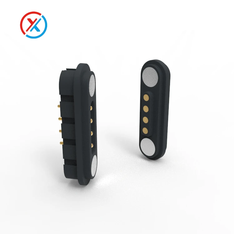
This arrangement can make charging easier when the device has limited space for an accessible socket. The contact layout, housing, and magnetic arrangement must work together so that attachment produces the correct alignment and working compression.
The design described here uses two contacts and an intended charging current of approximately 1.5 A. The final assembly rating should be confirmed under the specified electrical load, contact compression, and operating temperature.
| Design item | Configuration or requirement |
|---|---|
| Contact arrangement | Two contacts, normally assigned to power supply and return |
| Connection method | Magnetic attachment with spring-loaded electrical contacts |
| Intended charging current | Approximately 1.5 A, subject to validation of the selected assembly |
| Installation | Compact device-side interface matched to the tracker enclosure |
| Environmental considerations | Moisture, dirt, cleaning exposure, contact wear, and corrosion |
| Customization | Housing dimensions, contact position, working travel, magnet arrangement, and cable termination |
The connector carries current supplied by the charging system; it does not regulate battery charging itself. The power source, cable, tracker electronics, and battery-charging circuit must support the intended operating conditions.
Both supply and return paths contribute resistance. The evaluation should include the pogo pins, mating pads, terminations, cable, and PCB connections. Voltage drop and temperature under load provide a better indication of charging performance than continuity alone.
For a small tracker, enclosure temperature also matters. A connector tested in open air may dissipate heat differently when installed inside a compact plastic housing. Sample evaluation should therefore use a representative assembly.
Magnetic attachment can reduce the positioning effort needed to connect the charger. Its effectiveness depends on magnet placement, the approach direction, and the locating features around the contacts.
The housing should establish the final mating position and prevent the contacts from sliding onto unintended conductive areas. Magnet polarity can assist orientation, but magnetic attraction alone does not guarantee correct electrical polarity. The design needs to address reversed, offset, and partially engaged positions.
Contact force should be defined at the intended working compression. The spring travel can accommodate a specified variation in mating height, but it does not compensate for unrestricted sideways movement.
The dimensional review should include contact height, carrier position, enclosure thickness, and mating-pad location. At minimum compression, both contacts need adequate engagement. At maximum compression, mechanical stops should prevent overtravel.
Retention must also account for the combined spring force and cable loading. A cable hanging from one side of the tracker can create a different separating force from a straight pull. Attachment and release should be evaluated in the directions expected during normal handling.
Where controlled breakaway is required, the release behavior needs a defined target and test method. Magnetic separation may reduce some loads transmitted to the charging port, but it cannot be described as automatically safe under every pull condition. Its behavior concerns the charging lead and device interface; it does not establish the safety performance of the collar or harness.
Environmental exposure is another important part of the design. A tracker may encounter rain, humidity, dirt, skin oils, and cleaning residues. Moisture retained around the charging face can affect both the contacts and nearby metal components.
Corrosion resistance comes from the complete material and coating system. The contact substrate, surface preparation, underlayer, functional finish, and coating coverage all influence performance.
Gold over a suitable nickel underlayer is one possible contact finish, but the selected specification should follow the application requirements. A gold-colored surface does not establish plating thickness, wear resistance, or long-term corrosion performance.
The mating pads need attention as well. A well-finished pogo pin cannot compensate for an unsuitable or damaged mating surface. Both sides of the interface should be included in durability and environmental evaluation.
Magnet protection and retention form part of the assembly design. The housing should hold the magnets securely and protect them from the specified exposure. Seals, adhesives, and overmolding materials should remain compatible with the surrounding components.
An accessible contact face can make inspection and cleaning easier. Recesses may protect contacts from direct handling, but their geometry should avoid trapping unnecessary moisture or debris. Magnetic interfaces also need assessment for attracted ferrous particles that could interfere with seating or bridge exposed contacts.
A corrosion-resistant finish does not make the connector waterproof. Any ingress-protection requirement should identify the complete assembly and whether it applies while connected, disconnected, or covered.
Vibration resistance likewise depends on the installation. Spring-loaded contacts can maintain pressure within their working range, while the housing and retention features control relative movement. Repeated small movements may produce fretting, contact wear, or resistance changes even when the charging head remains attached.
Useful sample checks include:
Correct contact mapping and polarity in the intended mating position.
Engagement across the permitted dimensional tolerances.
Voltage drop and temperature at the specified charging current.
Retention and release under representative cable-loading directions.
Contact stability during the required movement conditions.
Wear, corrosion, and plunger return after the specified exposure and mating cycles.
Acceptance criteria should be established before testing. The evaluation should consider electrical performance and mechanical condition together, rather than relying on whether the tracker still indicates charging.
XINTENG supports drawing-based customization of pogo pin contacts, magnetic housings, insulating carriers, mating components, and charging cable assemblies. For a pet tracker, these elements can be coordinated around the enclosure, PCB position, mounting space, and intended cable routing.
Customization can address contact height, spacing, working travel, housing profile, magnet position, and termination method. Approved samples and inspection criteria should remain linked to the selected materials and part revisions so that production assemblies reflect the evaluated design.
1. Does the approximately 1.5 A specification mean the tracker always charges at 1.5 A?
No. Actual charging current depends on the power source, cable, device electronics, battery condition, and charging control. The connector must be validated for the intended current under its specified installation conditions.
2. Is this type of magnetic connector automatically waterproof?
No. Protection depends on the housing, seals, mounting interface, and cable entry. Connected and disconnected conditions may have different requirements and should be assessed separately.
3. Will the magnetic charging head always release safely when pulled?
Release depends on magnetic force, pull direction, cable routing, and housing geometry. A controlled breakaway function requires defined acceptance criteria and testing. It should not be treated as proof of collar or harness safety.
4. Can XINTENG customize the connector for a particular pet tracker?
Yes. Device drawings can guide the contact layout, housing dimensions, mounting features, magnet arrangement, and charging cable. Electrical requirements, environmental exposure, and intended release behavior help define the design and sample evaluation.


