


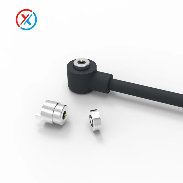
The first step is to identify which components actually need new tooling. A magnetic connector may combine machined contacts, an insulating carrier, magnets, a housing, seals, and a cable overmold. Customizing one part does not necessarily require a new mold for the entire assembly.
Pogo pin plungers and barrels can be developed through precision machining. A new injection mold may be needed for a different plastic carrier or housing, while a custom cable exit may require separate overmolding tooling. Some projects can use existing contacts and molded parts with limited modifications.
| Development route | When it may be suitable | Typical work involved |
|---|---|---|
| Standard connector | Available dimensions, ratings, and mounting meet the requirements | Confirming fit, electrical compatibility, and application performance |
| Modified standard assembly | The established interface works, but selected features need adjustment | Cable changes, terminations, mounting parts, or compatible component substitutions |
| Fully custom assembly | The required geometry or performance cannot be accommodated by existing parts | Contact development, new carriers or housings, tooling, fixtures, and validation |
Restricted installation space is a common reason to consider a custom design. A connector may need to fit a thin enclosure, follow a curved surface, align with an existing PCB, or clear a nearby component.
In these cases, the important dimensions extend beyond external length and width. Contact height, working compression, magnet seating depth, locating features, and mounting surfaces determine whether the assembled interface engages correctly.
A standard connector that fits inside the enclosure may still leave the pins insufficiently compressed or place them too close to the edge of the mating pads. A custom carrier or housing can address these relationships together.
Electrical requirements can also justify development. An application may need additional power contacts, separate returns, identification signals, or a different communication arrangement. Higher current may require changes to the conductive path, contact geometry, terminations, or thermal arrangement.
A new mold can provide space and positioning for those changes, but it does not independently establish current capacity or signal performance. The complete assembly must be evaluated at the specified working compression and operating conditions.
Contact assignments should therefore be settled early. Increasing the pin count without defining each function can create unnecessary size and tooling complexity. Conversely, an interface planned only for charging may need substantial revision if communication functions are added later.
Environmental protection is another reason to reconsider the construction. Moisture, sweat, dust, cleaning agents, and corrosion can require specific sealing surfaces, contact positioning, cable-entry features, or material choices.
These features may be difficult to add to a standard housing after its geometry has been fixed. Developing them into the carrier, enclosure interface, or overmold can provide a more controlled construction.
Protection targets need measurable acceptance criteria. A custom housing shape does not establish a waterproof or corrosion-resistance rating by itself. The specification should identify the relevant assembly condition, exposure method, and electrical or mechanical requirements after testing.
Appearance can influence tooling, particularly where the connector forms part of the visible product enclosure. A circular, rectangular, or racetrack-shaped interface may need a different molded housing. A dedicated cable exit or integrated locating feature can also affect the tool.
Colour, logos, and markings should be reviewed separately. Some appearance changes can be achieved without redesigning the molded geometry. The manufacturing review should distinguish cosmetic requirements from changes that affect fit, material behaviour, or function.
Assembly difficulties can make customization worthwhile even when the standard connector meets its individual specifications. Problems may include inaccessible fasteners, inconsistent positioning, an unsupported PCB connection, or insufficient clearance for cable installation.
Custom mounting features, locating surfaces, or supporting parts can simplify the assembly sequence. The design should establish where mechanical loads are carried so that contacts and electrical terminations remain within their permitted loading.
A dedicated interface may also require a specific contact pattern, orientation, or attachment behaviour. Housing keys and magnet polarity can assist correct mating, while mechanical guides control the final position.
Magnetic force should be considered alongside spring force, seal compression, cable loading, and the intended release direction. Selecting a stronger magnet alone does not resolve an unsuitable mating geometry.
Production quantity affects the tooling decision, but there is no universal order volume at which custom molding becomes economical. The calculation depends on tool complexity, materials, assembly labour, expected yield, validation, and the quantity over which the investment will be recovered.
Tooling cost divided by the expected accepted production quantity gives a basic amortized cost per assembly. That figure should be considered alongside the recurring manufacturing cost and the possibility of later design changes.
Small-volume projects can still justify custom components when the functional need is clear. Machined housings, existing molded parts, or prototype fixtures may provide a practical route to sample evaluation before production tooling is commissioned.
XINTENG supports drawing-based development of magnetic connectors, pogo pin contacts, insulating carriers, housings, mating components, and cable assemblies. An initial review can establish which requirements fit existing components and which require new parts or tooling.
A useful development package includes:
Dimensioned drawings, a 3D model, or a reference sample.
Available installation space and the device-side mating arrangement.
Contact count, spacing, assignments, and working height.
Operating voltage, continuous current, and peak-load conditions.
Required communication or identification functions.
Attachment, retention, and release requirements.
Mounting method, cable routing, and production assembly sequence.
Environmental exposure and validation targets.
Expected prototype, initial-order, and ongoing production quantities.
Target cost and required development schedule.
Before tooling release, the design review should settle the critical mating dimensions, material specifications, contact travel, magnetic arrangement, and inspection criteria. Mold shrinkage, part flatness, and assembly allowances need consideration where they affect the finished interface.
Prototype evaluation should use representative contacts and mating components. A printed housing can help check space and handling, but it may not reproduce the mechanical, thermal, or sealing behaviour of the production material.
The quotation should define the tooling scope, sample stages, acceptance process, expected lead time, and responsibility for revisions. Tool ownership, maintenance, and storage arrangements should also be agreed as commercial terms.
Approved samples and drawings then provide the production reference. Changes to the contact system, molded geometry, materials, or sealing arrangement require review against that reference.
1. Does every custom magnetic connector require a new mold?
No. Some requirements can be met with machined contacts, cable changes, custom mounting parts, or existing molded components. New tooling becomes necessary when the required geometry or manufacturing process cannot be supported by the available parts.
2. Is there a fixed minimum order quantity for custom tooling?
There is no universal minimum. Feasibility depends on the component design, tooling investment, manufacturing method, and production plan. Prototype and small-batch options should be reviewed separately from the long-term molded production route.
3. Can development begin without a complete 3D model?
Yes. A dimensioned sketch, 2D drawing, reference sample, and clear operating requirements can support an initial review. The necessary production drawings and critical dimensions should be agreed before tooling is released.
4. Does a new mold guarantee higher current capacity or waterproof performance?
No. Tooling establishes component geometry and supports manufacturing consistency. Electrical, thermal, mechanical, and environmental performance must be demonstrated on the relevant assembled configuration.


