


A meaningful rating describes the current an assembly can carry under specified conditions while remaining within its electrical, thermal, and mechanical limits. The same contact may perform differently in an open test fixture, a compact enclosure, or a densely loaded connector array.
Understanding those conditions helps engineers compare products and define custom requirements without relying on an isolated amperage figure.
The conductive path is the starting point. In a typical pogo pin, current passes through the plunger, internal contact interfaces, barrel, and termination. The exact route depends on the design.
The spring supplies mechanical force, but its role in conduction varies. It should not automatically be treated as either the main current path or completely excluded from it. Internal geometry determines how the components maintain contact during compression.
Larger conductive cross-sections can reduce bulk resistance when other conditions are comparable. Length matters too: a longer conductive path can increase resistance. However, the internal sliding interface and external mating contact introduce resistance that cannot be predicted from dimensions alone.
The mating surface deserves particular attention. Head shape, pad finish, alignment, contact force, and contamination affect how current crosses the interface. A larger visible contact face does not necessarily produce a proportional increase in effective electrical contact area.
Resistance limits current because it creates voltage drop and heat:
Voltage drop: V = I × R
Resistive heating: P = I² × R
For an illustrative path with 20 mΩ resistance, 5 A produces a 0.1 V drop and 0.5 W of heat. At 10 A, the same resistance produces a 0.2 V drop and 2 W of heat.
These are calculation examples, not product ratings. They show why increasing current places greater demands on resistance control and heat dissipation. The complete power circuit also includes the return path and its associated losses.
Material selection influences both electrical and mechanical performance. A higher-conductivity alloy can reduce bulk resistance, but the component still needs sufficient strength, dimensional stability, and manufacturability.
The spring material has a different set of priorities, including force retention and fatigue behaviour. Selecting a conductive material for one component does not establish the performance of the complete contact assembly.
Surface treatment primarily influences the contact interface and its stability over time. Gold over a suitable underlayer can help maintain a stable contacting surface, but coating thickness alone does not define current capacity.
Coverage, adhesion, wear, porosity, and the condition of the mating pad all matter. A thicker gold layer cannot compensate for an unsuitable conductive path, poor engagement, or inadequate cooling.
Working compression connects the mechanical design with electrical performance. Contact force varies as the plunger moves, so resistance and current testing need a defined installed position.
Insufficient compression may leave inadequate contact force. Excessive compression can damage components, accelerate wear, or impair movement. The useful operating range must accommodate assembly tolerances while preserving suitable engagement.
In multi-pin connectors, the combined spring force also affects the mounting structure. PCB or housing deflection can change compression across the array, leaving individual contacts in different operating conditions.
Heat dissipation is another major influence. PCB copper, wire dimensions, terminations, housing construction, airflow, and surrounding components determine how heat leaves the contact.
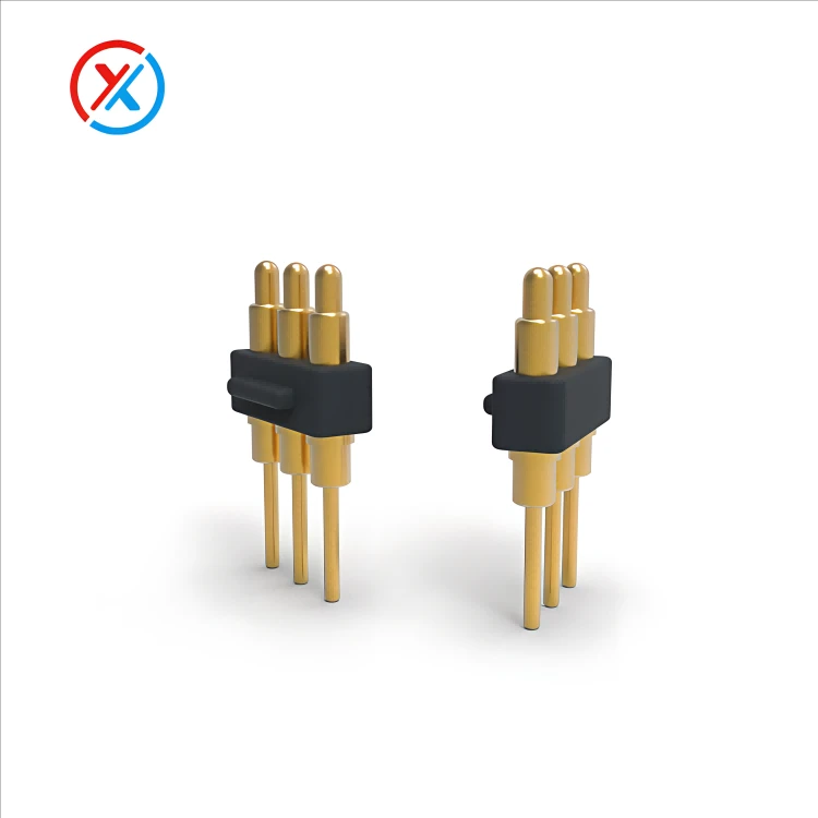
A pin tested individually in open air may not represent the same pin inside a sealed enclosure. Likewise, testing one energized contact does not establish the thermal behaviour of an array with several adjacent power contacts loaded simultaneously.
Ambient temperature reduces or increases the available thermal margin. At a higher starting temperature, less additional heating may be acceptable before a component reaches its specified limit. The relevant limits can involve the contacts, spring, insulator, seals, or nearby materials.
There is no universal permissible temperature rise for every pogo pin application. The criterion must be defined for the product and installation.
Parallel contacts can distribute current, but their ratings cannot simply be multiplied without evaluating the arrangement. Differences in contact resistance, compression, wiring length, and termination quality can produce unequal sharing.
One contact may carry more current than its neighbours. Thermal interaction between closely spaced contacts can further affect performance. Testing should therefore use the intended supply and return configuration with representative conductors and mounting.
Supply and return contacts also have different roles from parallel contacts. In a basic two-contact power circuit, both contacts carry the circuit current. Their individual ratings are not added together to obtain a larger circuit rating.
Continuous, peak, and pulsed loads require separate assessment. A brief peak may produce a different temperature response from sustained current, but pulse duration, repetition rate, duty cycle, and cooling time all matter.
Average current alone may not adequately describe a pulsed load. The supplier needs the operating waveform or a sufficiently detailed load profile to evaluate it. A peak-current value should not be interpreted as a continuous rating.
For product comparison, current data should identify the conditions behind the measurement:
| Rating condition | Information to confirm |
|---|---|
| Mechanical state | Installed compression, contact force, and mating components |
| Electrical load | Continuous current or defined pulse and peak conditions |
| Installation | PCB connection, wire size, terminations, housing, and airflow |
| Loaded configuration | Number and position of energized contacts, including returns |
| Thermal conditions | Ambient temperature, measurement locations, and acceptance limits |
| Sample condition | Whether testing uses new parts or specified preconditioned assemblies |
Long-term behaviour may also affect the usable current. Wear, contamination, corrosion, or reduced contact force can change resistance after service exposure. Where the application requires it, thermal and electrical evaluation should include appropriately aged or preconditioned samples.
XINTENG supports drawing-based customization of pogo pin contacts, insulating carriers, mounting parts, magnetic connector housings, and cable assemblies. Current requirements can be reviewed alongside the available space, conductive geometry, contact layout, working travel, and termination method.
For a custom project, provide the operating voltage, continuous current, peak-load profile, installed height, ambient conditions, and available heat paths. Allowable voltage drop and temperature limits help establish measurable development targets.
Prototype or small-batch evaluation can then assess the proposed assembly under representative conditions. The approved rating should remain linked to the tested materials, dimensions, mating parts, and installation rather than being treated as a property of pin diameter alone.
1. Does a thicker pogo pin always carry more current?
No. A larger cross-section may reduce bulk resistance, but internal contact structure, mating conditions, materials, terminations, and cooling also influence the rating. Compare complete designs under equivalent test conditions.
2. Will thicker gold plating increase the current rating?
Not automatically. Gold plating supports contact-surface stability, but current capacity depends on the entire conductive and thermal path. Thickness must be considered alongside coating quality, wear, contact force, and substrate design.
3. Can supply and return contact ratings be added together?
No. In a two-contact power circuit, supply and return both carry the same circuit current. Increasing capacity through parallel contacts requires a separate assessment of current sharing and temperature.
4. What information is needed to develop a custom high-current pogo pin connector?
Provide the drawings, installation space, working compression, voltage, continuous current, and peak or pulse profile. Include the termination arrangement, ambient temperature, loaded contact layout, allowable voltage drop, and thermal limits.


