







Large Diameter Pogo Pins
Dongguan Xinteng Electronics Co., Ltd. is one of the most reliable manufacturers and suppliers of large diameter pogo pins in China, featured by quality products and good service. Welcome to wholesale bulk durable large diameter pogo pins in stock here from our factory. Also, customized service and OEM&ODM service are available.
Large Diameter Pogo Pins Introduction
This pogo pin handles up to 10 amps, boasts a lifespan of 50,000 cycles, withstands 48 hours of salt spray testing, and is vibration and water-resistant.
Pogo pins are surface-mounted (SMT) and can be mounted directly on the PCB surface, eliminating the need for through-hole mounting. This reduces connector footprint, making them suitable for high-speed mass production and lowering labor costs. The pogo pins are gold-plated to reduce contact resistance and energy loss. They are suitable for high-current connections in battery modules, charging connector ports, motor controllers, robotic joints, and 3D printers.
Product Parameters
|
Product model |
RG-1343 |
|
Mechanical |
|
|
Contact force |
160g±20g at 1.2mm working storke Full storke 1.4mm |
|
Life test |
50,000 cycles |
|
Electrical |
|
|
Rated voltage |
DC 12V |
|
Rated current |
10A Max |
|
Contact resistance of spring pin |
50 milliohm Max |
|
Environmental performance |
|
|
Operation Temperature |
-25℃ to +60℃ |
|
Salt Spray |
48H |
|
Packing |
PE bag / reel packing |
| Material and coating conform to ROHS and REACH standards | |
Product details
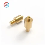
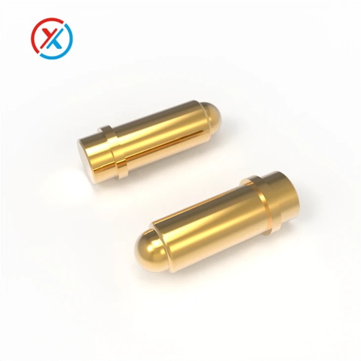
The large diameter pogo pins have a needle diameter of 2.40 mm and a total height of 8.80 mm. They have a beveled cross-section needle with a built-in insulating bead. The single-needle contact impedance is less than 50 milliohms. The spring force is 160g ± 20% at a working pressure of 1.20 mm and the maximum stroke is 1.40 mm.

Precautions for using pogo pin
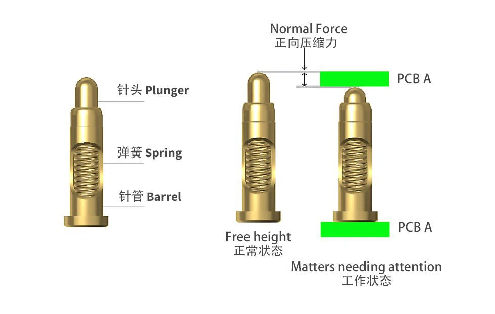
- Los planos de ingeniería indicarán un valor de compresión adecuado, generalmente 2/3 de pulgada de la carrera total. Una presión y empuje insuficientes provocarán una impedancia inestable; por el contrario, una presión excesiva dañará la abertura del tubo, causando que los contactos de los pines de contacto se bloqueen.
- Durante el montaje, se debe tener cuidado de no aplicar una fuerza excesiva en la abertura del tubo, ya que esto podría causar deformación y bloquear los contactos de los pines de contacto.
- Los contactos de la batería que se acoplan con los pines de contacto o los contactos dorados del FPC deben estar libres de suciedad, oxidación, etc., para garantizar una conexión estable.
Contact Resistance
Testing the contact resistance of a pogo pin is typically done using the four-terminal measurement method. Contact resistance measurement is crucial to ensuring the stability and reliability of the pogo pin's electrical connection, especially in high-frequency, low-voltage, or high-power applications. The following are the specific steps and methods for measuring pogo pin contact resistance:
1. Four-Terminal Measurement (Kelvin Measurement)
The four-terminal measurement method is a highly accurate measurement method that effectively eliminates interference from wire resistance and ensures the true contact resistance of the pogo pin.
- Steps:
- Equipment Preparation:
A high-precision digital multimeter (or ohmmeter) and a four-terminal test fixture (Kelvin fixture) are required. The four-terminal test fixture transmits the test current and voltage through different contact points, preventing the voltage drop caused by the current flowing through the wires from affecting the contact resistance measurement.
- Connecting the Test Instrument:
Connect the four terminals of the four-terminal test fixture to the measurement terminals of a test instrument (such as a digital multimeter).
The two terminals are current terminals: Current is transmitted through these two terminals.
Both ends are voltage terminals: Used to measure voltage drop.
- Installing a Pogo Pin:
Secure the Pogo Pin in the measurement fixture, ensuring that its contact terminals are in good contact with the test voltage and current terminals.
- Measuring Voltage Drop:
Apply a known, low current (usually in the microampere or milliampere range) through the Pogo Pin and measure the voltage drop. Using Ohm's law (V = IR), the current and voltage drop can be used to calculate the contact resistance.
- Calculating Contact Resistance:
Contact Resistance (R) = Measured Voltage (V) / Test Current (I).
For example, if the voltage drop is 0.1V and the current is 1mA, the contact resistance is 0.1V / 0.001A = 100Ω.
- Advantages:
The four-terminal measurement method accurately measures the contact resistance of a Pogo Pin, eliminating the influence of lead resistance and providing a true measurement value.
Suitable for precision measurements, especially for testing low contact resistance.
2. Use a Contact Resistance Tester
Specialized contact resistance testers are commercially available. These devices typically automatically apply current, measure voltage drop, and then calculate contact resistance. Their advantage is their high degree of automation, making them suitable for high-volume testing.
- Steps:
Connect the Pogo Pin to the tester to ensure good contact between the electrodes and the contact points.
Measure and record the current and voltage drop.
The contact resistance value is automatically calculated and displayed.
This method is suitable for quality control in mass production, as it is fast and accurate.
- Summary:
The four-terminal Kelvin method is typically used to test the contact resistance of a Pogo pin. This method effectively eliminates interference from wire resistance and ensures accurate measurements. Alternatively, a specialized contact resistance tester can be used for rapid, automated testing. These methods ensure that the Pogo pin's electrical performance meets design requirements, ensuring connection stability and long-term reliability.
FAQ
Hot Tags: large diameter pogo pins, China large diameter pogo pins manufacturers, suppliers, factory, Pogo Pins, mini pogo pins, pcb mount pogo pins, pogo pin, pogopins, pogo pin 2mm
Previous
SMD Pogo PinsNext
Pin PogoYou Might Also Like


Send Inquiry